
Technical data

Chapter 5 99
Spectrum Analyzer
Making Distortion Measurements
Spectrum Analyzer
Third-Order Intermodulation Distortion
Two-tone, third-order intermodulation distortion is a common test in
communication systems. When two signals are present in a non-linear
system, they can interact and create third-order intermodulation
distortion products that are located close to the original signals. These
distortion products are generated by system components such as
amplifiers and mixers.
This procedure tests a device for third-order intermodulation using
markers. Two sources are used, one set to 300 MHz and the other to
301 MHz.
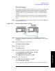
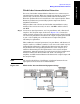
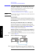
Step 1. Connect two signal generators, two low pass filters, and a directional
coupler to the analyzer input as shown in Figure 5-23. Connect the
output of signal generator #1 to port 2 of the directional coupler through
one of the low pass filters and connect the output of signal generator #2
to port 3 (the coupled port) of the directional coupler through the
remaining low pass filter.
This combination of signal generators, low pass filters, and directional
coupler (used as a combiner) results in a two-tone source with very low
intermodulation distortion. Although the distortion from this setup
may be better than the specified performance of the analyzer, it is
useful for determining the TOI performance of the source/analyzer
combination. After the performance of the source/analyzer combination
has been verified, the device-under-test (DUT) (for example, an
amplifier) would be inserted between the directional coupler output and
the analyzer input.
NOTE The coupler should have a high degree of isolation between the two
input ports so the sources do not intermodulate.
Figure 5-23 Third-Order Intermodulation Equipment Setup