
Technical data

100 Chapter 5
Spectrum Analyzer
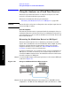
Making Distortion Measurements
Spectrum Analyzer
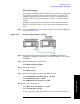
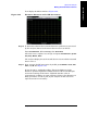
Step 2. Set the signal sources as follows:
Set signal generator #1 to 295 MHz at –5 dBm. Set signal generator #2
to 296 MHz at 11 dBm (this higher power level overcomes the nominal
16 dB loss through the coupled arm of the directional coupler). This will
result in a frequency separation of 1 MHz.
The amplitude of both signals should be approximately −5dBm at the
output of the bridge.
Step 3. Set the analyzer center frequency and span:
Press
Mode Preset.
Press
FREQ Channel, Center Frequency, 295.5, MHz.
Press
SPAN X Scale, Span, 5, MHz.
Press
AMPTD Y Scale, Elec Atten, 10, dB.
Step 4. Reduce the RBW until the distortion products are visible:
Press
BW, Res BW (Manual), ↓.
Step 5. Move the signal to the reference level:
Press
Peak Search, Marker →, Mkr →RL.
Step 6. Calculate the attenuator setting required for a –30 dBm mixer level
based upon the current reference level setting: Atten = Ref Level –
(–30 dBm)
Press
AMPTD Y Scale, Elec Atten, enter the attenuation value for the
calculation above and press
dB.
Step 7. Reduce the RBW until the distortion products are visible:
Press
BW, Res BW (Manual), ↓.
Step 8. Turn on averaging to increase the visibility of the distortion products:
Press
Avg Mode, Exponential, Avg Number, 10, Enter.
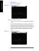
Step 9. Activate the second marker and place it on the peak of the distortion
product (beside the test signal) using the
Next Peak key.
Press
Peak Search, Marker, Delta, Peak Search, Next Peak (active marker
should be on the other input signal),
Next Peak (active marker should be
on a distortion product).
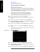
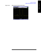
Step 10. Measure the other distortion product:
Press
Next Peak. (see Figure 5-24)