
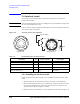
Technical data

Agilent B1500A Configuration and Connection Guide, Edition 5 3- 21
Connection Guide for Wafer Prober
WGFMU and RSU
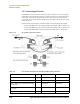
3.5.2 Connecting RF Probes
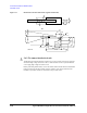
The RF measurement system supports the measurement of the three-terminal MOSFET
(source and well (substrate) are shorted) by using the RF probes as shown in
Figure 3-22.
One measurement path is for the gate terminal and the other path is for the drain terminal.
Moreover, the source/well terminal must be electrically connected to the ground via the
shielding of the measurement path (RF probes and measurement cables). See
Figure 3-23.
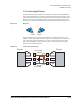
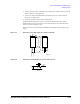
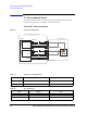
Figure 3-22 RF probes
Prepare two RF probes to perform the RF measurement. The RF probe must have the
signal line and the ground lines as shown in
Figure 3-23. The signal line is to connect the
gate or drain pad, and the ground lines are to connect the source/well pads. For the RF
probe and its installation, consult your favorite prober vender.
Figure 3-22 shows RF
probes from Cascade Microtech, Inc.
Figure 3-23 Contact Pad and Probe Tip
to Drain
to Gate
Signal
Gnd
Gnd
Signal
Gnd
Gnd
Gate
Drain
RF probe
RF probe
Source/Well
Source/Well