
Technical data

3- 28 Agilent B1500A Configuration and Connection Guide, Edition 5
Connection Guide for Wafer Prober
Interlock circuit
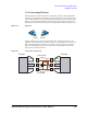
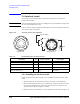
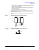
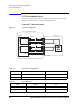
Figure 3-31 Dimensions of the Interlock Switch (Agilent N1254A-402)
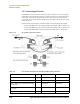
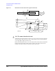
3.6.2 To connect interlock circuit
The B1500A provides the Interlock connector to prevent you from receiving an electrical
shock from high voltage (more than ± 42 V). If the interlock circuit is open, the B1500A
cannot apply high voltage more than ± 42 V.
Before performing measurement, connect the 16493J interlock cable between the B1500A
Interlock connector and the interlock connector which is a part of the interlock circuit
installed in your DUT interface as described in the previous section.
3.1
59.4
8.1
10
NC
NO
COM
6.35
22.2
27.8
37.8
2.8
6.5
5.5
15.9
18.8
4.75
10.3
4.3
2.8
2.8
Max 9
15.2
10.3
2.8
3.1
Switch off
Switch on
Units: mm