
Technical data

Module 9
Modifying Application Test Definitions
9-7
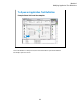
To Modify Test Definition
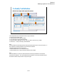
Change default values and add parameters (ex: Pcomp_d)
This area sets the
properties of the
specified parameter.
•Min
•Max
•Digits
•Resolution
•Unit
•Typical Values
•Symbols
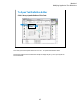
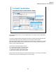
Test Definition editor
On the Test Specification tab screen, you can add new parameters or change parameter settings.
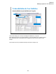
This example changes the default value of the Module parameters for the MOS FET class exercise
typical setup and adds the Pcomp_d test parameter (drain terminal power compliance).
The Module parameter default values are changed as follows. See the actual settings on the test
definition editor.
Drain: SMU4
Gate: SMU3
Source: SMU2
Subs: SMU1
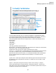
The Pcomp_d parameter is defined as follows.
Name=Pcomp_d, Type=Numeric, Default=1 mW, Description=Power compliance for drain terminal,
Align=check, X=550, Y=120, Width=80, Ext=uncheck
Properties: Min=1 mW, Max=20 mW, Digits=4, Resolution=1 mW, Unit=W
For Align, X, Y, and Width values, consult the settings of the other parameters for the same terminal
(ex. Drain). For example, Pcomp_d must be located between Vd and Subs entry fields (see
application test screen on the main window). So X and Width should be the same as the settings of
Vd, and Y should be between 90 and 180 (see the actual settings of Vd and Subs on the test
definition editor).
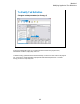
Typical Values… button opens a dialog box used to define the typical values used for the selections
of the parameter value in the Application Test mode. For example, set 2 mW to 20 mW in 2 mW
step for Pcomp_d.
Symbols… button opens a dialog box used to map a numeric value to a string. For example,
Value=1 and Symbol=ON are set, typing ON enters 1, and typing 1 enters ON. The value must
satisfy the Min, Max, Digits, and Resolution settings. The value and the symbol must be one by one.
The definition is effective only for the parameter.