
Installation guide

26 16900 Series Logic Analysis Systems Installation Guide
2 Installing Logic Analyzer Cards and Probes
To install, remove, or replace measurement modules
If you ordered your measurement modules with the frame, they will
already be installed and you can skip this procedure.
If you are using a measurement module from a 16700 Series logic analysis
system you will need to replace the thumb screws. Begin with the
instructions on page 24.
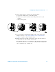
The following procedure guides you through installing, removing, or
replacing measurement modules in the logic analysis system frame.
Information on connecting specific multi- card measurement modules is in
the next sections of this chapter. Measurement modules with different
model numbers cannot be connected together in multi- card
(Master/Expander) modules unless stated otherwise.
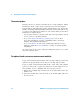
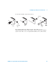
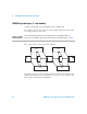
1 Power down the system and disconnect the power cable before
installing, removing or replacing measurement modules.
CAUTION
Electrostatic discharge can damage electronic components. Use grounded wrist straps
and mats when performing any service to measurement modules.
CAUTION
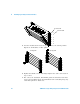
When removing cards that are connected together as multiple-card modules, be sure
to eject the multiple cards simultaneously, otherwise, the flex cables and/or
connectors could be damaged.
Power Off
Disconnect
Disconnect
OR