
Installation guide

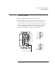


Table Of Contents
- A Quick Tour
- Before You Begin
- Introduction to Timing Analysis: Trigger on an Edge
- Verify Pulse Widths
- Introduction to State Analysis: Trigger on an Event
- Trigger on a Sequence of Events
- Trigger on a 4 Bit Serial Pattern
- Trigger the Oscilloscope with the Timing Analyzer
- Load the RESET Configuration File
- Connect the Oscilloscope Probe and Turn the Glitch On
- Get the Analog Waveform on the Display
- Set Up the Timing Analyzer
- Set Up the Timing Analyzer to Trigger on the Glitch
- Tell the Oscilloscope When to Trigger
- Set Up the Analyzer to Arm the Oscilloscope
- Run the Timing Analyzer and Oscilloscope
- Add the Analog Waveform to the Timing Waveform
- Turn the Glitch Off
- Save Your Work
- Lesson Summary
- Using the Pattern Generator
- Load the RESET Configuration File
- Connect the Pattern Generator
- Set Up the Timing Analyzer
- Set Up the Bus Labels
- Define the Trigger Conditions: Trigger on a 1
- Set Up the Pattern Generator
- Program the Pattern Generator Output
- Start the Pattern Generator and View the Walking Ones Pattern
- Stop the Pattern Generator
- Save Your Work
- Lesson Summary
- Setting the Jumpers
- About the Credit Card Board

Hewlett-Packard
P.O. Box 2197
1900 Garden of the Gods Road
Colorado Springs, CO 80901-2197, U.S.A.
© Copyright Agilent Technologies
1998 All Rights Reserved.
Reproduction, adaptation, or
translation without prior written
permission is prohibited, except
as allowed under the copyright
laws.
Restricted Rights Legend
Use, duplication, or disclosure by
the U.S. Government is subject to
restrictions set forth in
subparagraph (C) (1) (ii) of the
Rights in Technical Data and
Computer Software Clause in
DFARS 252.227-7013. Agilent
Technologies, 3000 Hanover
Street, Palo Alto, CA 94304 U.S.A.
Rights for non-DOD U.S.
Government Departments and
Agencies are set forth in FAR
52.227-19 (c) (1,2).
Document Warranty
The information contained in this
document is subject to change
without notice.
Agilent Technologies makes
no warranty of any kind with
regard to this material,
including, but not limited to,
the implied warranties of
merchantability or fitness for
a particular purpose.
Agilent Technologies shall not be
liable for errors contained herein
or for damages in connection with
the furnishing, performance, or
use of this material.
Safety
This apparatus has been designed
and tested in accordance with
IEC Publication 1010, Safety
Requirements for Measuring
Apparatus, and has been supplied
in a safe condition. This is a
Safety Class I instrument
(provided with terminal for
protective earthing). Before
applying power, verify that the
correct safety precautions are
taken (see the following
warnings). In addition, note the
external markings on the
instrument that are described
under "Safety Symbols."
Warning
• Before turning on the
instrument, you must connect the
protective earth terminal of the
instrument to the protective
conductor of the (mains) power
cord. The mains plug shall only be
inserted in a socket outlet
provided with a protective earth
contact. You must not negate the
protective action by using an
extension cord (power cable)
without a protective conductor
(grounding). Grounding one
conductor of a two-conductor
outlet is not sufficient protection.
• Only fuses with the required
rated current, voltage, and
specified type (normal blow, time
delay, etc.) should be used. Do
not use repaired fuses or short-
circuited fuseholders. To do so
could cause a shock of fire hazard.
• Service instructions are for
trained service personnel. To
avoid dangerous electric shock,
do not perform any service unless
qualified to do so. Do not attempt
internal service or adjustment
unless another person, capable of
rendering first aid and
resuscitation, is present.
• If you energize this instrument
by an auto transformer (for
voltage reduction), make sure the
common terminal is connected to
the earth terminal of the power
source.
• Whenever it is likely that the
ground protection is impaired,
you must make the instrument
inoperative and secure it against
any unintended operation.
• Do not operate the instrument
in the presence of flammable
gasses or fumes. Operation of any
electrical instrument in such an
environment constitutes a definite
safety hazard.
• Do not install substitute parts or
perform any unauthorized
modification to the instrument.
• Capacitors inside the
instrument may retain a charge
even if the instrument is
disconnected from its source of
supply.
Safety Symbols
Instruction manual symbol: the
product is marked with this
symbol when it is necessary for
you to refer to the instruction
manual in order to protect against
damage to the product.
Hazardous voltage symbol.
Earth terminal symbol: Used to
indicate a circuit common
connected to grounded chassis.
WARNING
The Warning sign denotes a
hazard. It calls attention to a
procedure, practice, or the like,
which, if not correctly performed
or adhered to, could result in
personal injury. Do not proceed
beyond a Warning sign until the
indicated conditions are fully
understood and met.
CAUTION
The Caution sign denotes a
hazard. It calls attention to an
operating procedure, practice, or
the like, which, if not correctly
performed or adhered to, could
result in damage to or destruction
of part or all of the product. Do
not proceed beyond a Caution
symbol until the indicated
conditions are fully understood or
met.
!