
Installation guide

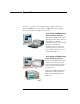


Table Of Contents
- A Quick Tour
- Before You Begin
- Introduction to Timing Analysis: Trigger on an Edge
- Verify Pulse Widths
- Introduction to State Analysis: Trigger on an Event
- Trigger on a Sequence of Events
- Trigger on a 4 Bit Serial Pattern
- Trigger the Oscilloscope with the Timing Analyzer
- Load the RESET Configuration File
- Connect the Oscilloscope Probe and Turn the Glitch On
- Get the Analog Waveform on the Display
- Set Up the Timing Analyzer
- Set Up the Timing Analyzer to Trigger on the Glitch
- Tell the Oscilloscope When to Trigger
- Set Up the Analyzer to Arm the Oscilloscope
- Run the Timing Analyzer and Oscilloscope
- Add the Analog Waveform to the Timing Waveform
- Turn the Glitch Off
- Save Your Work
- Lesson Summary
- Using the Pattern Generator
- Load the RESET Configuration File
- Connect the Pattern Generator
- Set Up the Timing Analyzer
- Set Up the Bus Labels
- Define the Trigger Conditions: Trigger on a 1
- Set Up the Pattern Generator
- Program the Pattern Generator Output
- Start the Pattern Generator and View the Walking Ones Pattern
- Stop the Pattern Generator
- Save Your Work
- Lesson Summary
- Setting the Jumpers
- About the Credit Card Board

15
Chapter 1: A Quick Tour
When Should I Use a Logic Analyzer?
In general, a logic analyzer is useful when you are beyond the
parametric stage of design, and you are interested in timing
relationships among many signals and need to trigger on logical highs
and lows. Logic analyzers are particularly useful when looking at timing
relationships or data on a bus. It can decode the information on
microprocessor busses and present it in a meaningful form.
What is a Logic Analyzer?
Logic analyzers grew out of oscilloscopes. They present data in the
same general way that an oscilloscope does; the horizontal axis is time,
the vertical axis is voltage amplitude. But a logic analyzer does not
provide as much voltage resolution or time interval accuracy as the
oscilloscope. Instead, it can capture and display dozens or more signals
at once - something that an oscilloscope cannot do.
A logic analyzer reacts the same way as your logic circuit does when a
single threshold is crossed by a signal in your system. It will recognize
the signal to be either high or low. The analyzer can also trigger on
patterns of highs and lows on these signals.
Up to now, the term “logic analyzer” has been used rather loosely. In
fact, a logic analyzer can be configured as a timing analyzer, a state
analyzer, a state and timing analyzer, or as two state analyzers.
What’s a Timing Analyzer? A timing analyzer is analogous to an
oscilloscope. It samples at regular time intervals, and displays the
information in a waveform similar to the oscilloscope. Because the
waveforms on both instruments are time-dependent, the displays are
said to be in the “time domain”.
What’s a State Analyzer? A state analyzer samples when you tell it
to using an external clock. Each time the state analyzer receives a state
clock pulse, it samples and stores the logic state of the system under
test. The data can then be viewed as a sequential listing of logical
states.