
Installation guide

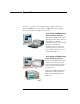
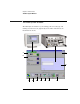


Table Of Contents
- A Quick Tour
- Before You Begin
- Introduction to Timing Analysis: Trigger on an Edge
- Verify Pulse Widths
- Introduction to State Analysis: Trigger on an Event
- Trigger on a Sequence of Events
- Trigger on a 4 Bit Serial Pattern
- Trigger the Oscilloscope with the Timing Analyzer
- Load the RESET Configuration File
- Connect the Oscilloscope Probe and Turn the Glitch On
- Get the Analog Waveform on the Display
- Set Up the Timing Analyzer
- Set Up the Timing Analyzer to Trigger on the Glitch
- Tell the Oscilloscope When to Trigger
- Set Up the Analyzer to Arm the Oscilloscope
- Run the Timing Analyzer and Oscilloscope
- Add the Analog Waveform to the Timing Waveform
- Turn the Glitch Off
- Save Your Work
- Lesson Summary
- Using the Pattern Generator
- Load the RESET Configuration File
- Connect the Pattern Generator
- Set Up the Timing Analyzer
- Set Up the Bus Labels
- Define the Trigger Conditions: Trigger on a 1
- Set Up the Pattern Generator
- Program the Pattern Generator Output
- Start the Pattern Generator and View the Walking Ones Pattern
- Stop the Pattern Generator
- Save Your Work
- Lesson Summary
- Setting the Jumpers
- About the Credit Card Board
18
Chapter 1: A Quick Tour
The Measurement Process
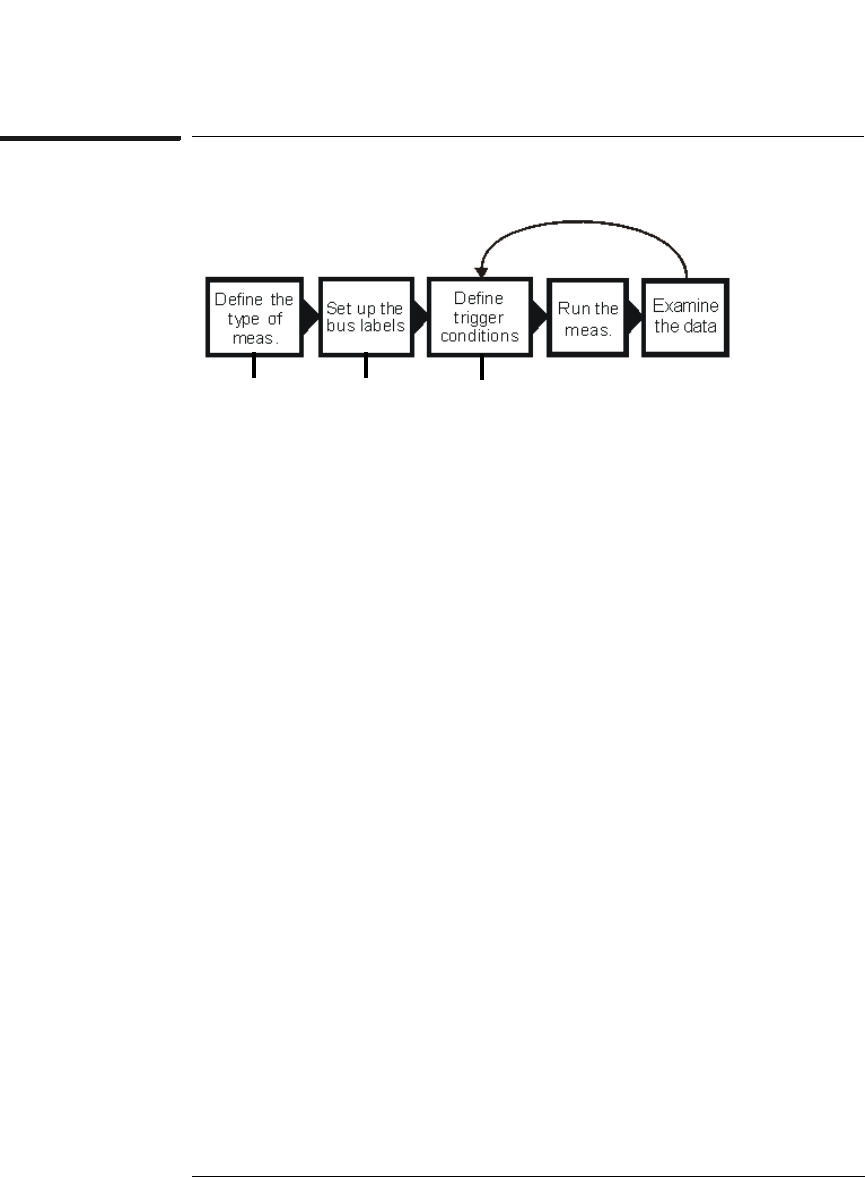
The Measurement Process
Define the type of measurement. Define how you want to sample
data by selecting state mode or timing mode, and by setting up the
state clock.
Set up the bus labels. Specify which signals you want to analyze by
grouping and labeling the signals.
Define trigger conditions. Define the trigger conditions and events
to control what the analyzer captures.
Run the measurement. Capture the data specified by the trigger
conditions.
Examine the data. Use the waveform or listing windows to search,
mark, and measure the data. It is common to go back and modify the
trigger conditions to capture different data.
Sampling
tab
Format
tab
Trigger
tab