
Specifications

101
Chapter 1: Agilent Technologies 16700A/B-Series Logic Analysis System
Adjusting Intermodule Skew
Adjusting Intermodule Skew
Skew is a small timing deviation between instruments configured in an
intermodule measurement. It is usually due to variances in internal
probing delays from one instrument to another. When desired, you
should adjust skew after new acquisitions are displayed.
The purpose of adjusting skew is to visually align waveforms in the
display so you can mark data or look for eye patterns within the
context of all displayed data sets.
In the following example, a Timing analyzer (bit 0) and an oscilloscope
(ch 1) are connected to the same glitch signal. Both waveforms are
displayed in the same Waveform display.
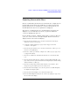
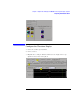
1. From the System window, choose the Select field in the desired logic
analyzer icon, then select Setup....
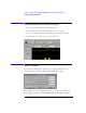
2. Configure a timing analyzer (see page 102) to trigger on the first
occurrence of the glitch.
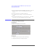
3. From the System window, choose the Select field in the oscilloscope icon,
then select Setup/Display.
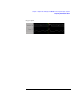
4. From the oscilloscope window, configure the oscilloscope (see page 103)
to trigger immediately.
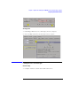
5. From the Icon Bar in the main System window, select the Intermodule
icon.
6. From the Intermodule window, configure the Group Run Arming Tree (see
page 104) so the Group Run field arms the timing analyzer and the timing
analyzer arms the oscilloscope.
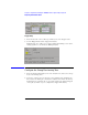
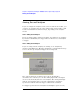
7. From the menu bar in the Intermodule window, select Window, then
Analyzer N (your analyzer), then select Waveform....
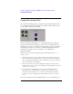
8. From the Waveform display, select the Group Run icon. This will update
the display showing the glitch.
9. From the Waveform display, select the Mixed Signal tab.
10. From the Mixed Signal tab, import the oscilloscope signal (see page 105)
into the Waveform display.