
Specifications

80
Chapter 1: Agilent Technologies 16700A/B-Series Logic Analysis System
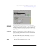
Overview - Multiple Frames Configuration
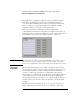
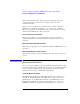
Frame 2 is an in-line frame. It has an input and output cable. The
output cable always connects into the input connector of the
downstream frame.
Frame 3 is the end frame. An end frame has no output cable. Each
Multi-frame configuration must have one, and only one end frame.
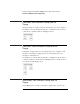
There is a picture associated with the above error that shows a daisy-
chain 3-frame Multi-frame cable connection.
Error communicating on the network
This message will be accompanied with the specific host that is
experiencing errors, with a messaged passed up from the low level
network.
Multi-frame: Required Network not enabled
This message appears if no networking is enabled and Multi-frame is in
the frame.
Multi-frame Network has not been validated
This message is printed on powerup when the cables have never been
tested.
Multi-frame Installation
Because the frame MUST be turned off during module installation, this
help system will not be available. Please refer to the Installation Guide
for the complete installation process when frame power is off. The
following is an overview of Multi-frame installation.
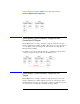
Connecting Mainframes Together
The Multi-frame module is installed into slot 1 in the rear panel of a
16700B or 16702B mainframe. The Multi-frame cable connects the
OUTPUT port of one Multi-frame module to the INPUT port of the
Multi-frame module in the adjacent frame. Frames are connected
OUTPUT to INPUT in a daisy chain until all frames are connected.