
User's Manual


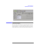
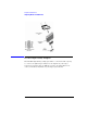
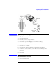
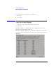
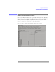
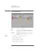
Table Of Contents
- Agilent Technologies 16750A/B Logic Analyzer
- Agilent Technologies 16750A/B Logic Analyzer
- Contents
- Getting Started
- Step 1. Connect the logic analyzer to the device under test
- Step 2. Choose the sampling mode
- Step 3. Format labels for the probed signals
- Step 4. Define the trigger condition
- Step 5. Run the measurement
- Step 6. Display the captured data
- For More Information...
- Example: Timing measurement on counter board
- Example: State measurement on counter board
- Task Guide
- Probing the Device Under Test
- Choosing the Sampling Mode
- To select transitional timing or store qualified
- Formatting Labels for Logic Analyzer Probes
- Setting Up Triggers and Running Measurements
- Displaying Captured Data
- Using Symbols
- Printing/Exporting Captured Data
- Cross-Triggering
- Solving Logic Analysis Problems
- Saving and Loading Logic Analyzer Configurations
- Reference
- The Sampling Tab
- The Format Tab
- Importing Netlist and ASCII Files
- The Trigger Tab
- The Symbols Tab
- Error Messages
- Must assign Pod 1 on the master card to specify actions for flags
- Branch expression is too complex
- Cannot specify range on label with clock bits that span pod pairs
- Counter value checked as an event, but no increment action specified
- Goto action specifies an undefined level
- Maximum of 32 Channels Per Label
- Hardware Initialization Failed
- Must assign another pod pair to specify actions for flags
- No more Edge/Glitch resources available for this pod pair
- No more Pattern resources available for this pod pair
- No Trigger action found in the trace specification
- Slow or Missing Clock
- Timer value checked as an event, but no start action specified
- Trigger function initialization failure
- Trigger inhibited during timing prestore
- Trigger Specification is too complex
- Waiting for Trigger
- Analyzer armed from another module contains no "Arm in from IMB" event
- Specifications and Characteristics
- Concepts
- Understanding Logic Analyzer Triggering
- Understanding State Mode Sampling Positions
- Getting Started
- Glossary
- Index

121
Chapter 3: Reference
Importing Netlist and ASCII Files
Importing Netlist and ASCII Files
Netlist Files
The Netlist Import feature provides a method for importing busses and
signals from ASCII netlists created by EDA tools. In order for the
feature to work, the device under test must either use the Agilent
E5346A high density adapter or the Agilent Technologies Termination
Adapter. The adapter must be included as a connector in the netlist.
You can create a Netlist file using an EDA tool. When importing a
Netlist file, you can specify which connectors are of interest;
connectors that are not specified will be ignored.
Example
NET'/Bus1(3)'J1-7
Bus1 Four bit bus
(3) Bit 3
J1-7 Connector J1, pin 7
To Import a Net List
1. Configure the connector names referenced in the Netlist to logic analyzer
pods.
2. Specify the Net List file to import.
3. Verify that Nets were correctly mapped to Labels, Pods, and Channels.
4. Select or create labels to appear in the interface.
Map the Connector Names (see page 127).
Import the Net List File (see page 127)
Verify Net to Label Mapping (see page 128)
Select/Create Interface Labels (see page 129)
ASCII Files
You can create an ASCII file using any Windows, MS-DOS, or UNIX text
editor. The ASCII file should contain bus names, pod/clock numbers,
and channel definitions.