
User's Manual


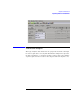

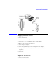
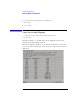
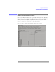
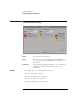
Table Of Contents
- Agilent Technologies 16750A/B Logic Analyzer
- Agilent Technologies 16750A/B Logic Analyzer
- Contents
- Getting Started
- Step 1. Connect the logic analyzer to the device under test
- Step 2. Choose the sampling mode
- Step 3. Format labels for the probed signals
- Step 4. Define the trigger condition
- Step 5. Run the measurement
- Step 6. Display the captured data
- For More Information...
- Example: Timing measurement on counter board
- Example: State measurement on counter board
- Task Guide
- Probing the Device Under Test
- Choosing the Sampling Mode
- To select transitional timing or store qualified
- Formatting Labels for Logic Analyzer Probes
- Setting Up Triggers and Running Measurements
- Displaying Captured Data
- Using Symbols
- Printing/Exporting Captured Data
- Cross-Triggering
- Solving Logic Analysis Problems
- Saving and Loading Logic Analyzer Configurations
- Reference
- The Sampling Tab
- The Format Tab
- Importing Netlist and ASCII Files
- The Trigger Tab
- The Symbols Tab
- Error Messages
- Must assign Pod 1 on the master card to specify actions for flags
- Branch expression is too complex
- Cannot specify range on label with clock bits that span pod pairs
- Counter value checked as an event, but no increment action specified
- Goto action specifies an undefined level
- Maximum of 32 Channels Per Label
- Hardware Initialization Failed
- Must assign another pod pair to specify actions for flags
- No more Edge/Glitch resources available for this pod pair
- No more Pattern resources available for this pod pair
- No Trigger action found in the trace specification
- Slow or Missing Clock
- Timer value checked as an event, but no start action specified
- Trigger function initialization failure
- Trigger inhibited during timing prestore
- Trigger Specification is too complex
- Waiting for Trigger
- Analyzer armed from another module contains no "Arm in from IMB" event
- Specifications and Characteristics
- Concepts
- Understanding Logic Analyzer Triggering
- Understanding State Mode Sampling Positions
- Getting Started
- Glossary
- Index

122
Chapter 3: Reference
Importing Netlist and ASCII Files
For Example
Label1;A2[15:5];A1[5,2]
Label1 Bus Name
A2 and A1 Pod Numbers
[15:5] Channel 15 through Channel 5 ("***********.....")
[5,2] Channel 5 and Channel 2 ("..........*..*..")
When setting up the ASCII file a comma (",") separates individual
channels, while a colon (":") creates a range of channels.
The following provides an explanation of how to setup and import
ASCII files into a logic analysis system.
Setting Up ASCII Files
NOTE: If the analyzer is in state mode with the Clock Setup Mode set to
demultiplexer, slave pods will appear with an "S" in front of the pod
designation.
For example:
Label1;SA2[5] reads as Label1 maps to Slave Pod A2 Channel 5.
Individual channels
Label1;A2[5] Label1 maps to Pod A2, Channel 5
Multiple channels
Label1;A1[5:2,0] Label1 maps to Pod A1, Channel 5 through Channel 2 and
Channel 0.
Individual channels on different pods
Label1;A2[1];A1
[0] Label1 maps to Pod A2, Channel 1 and Pod A1, Channel 0.
Multiple channels on different pods
Label1;A3[15:5];
A2[5];A1[6] Label1 maps to Pod A3, Channel 15 through Channel 5,