
User's Manual
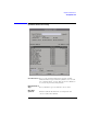
Table Of Contents
- Agilent Technologies 16750A/B Logic Analyzer
- Agilent Technologies 16750A/B Logic Analyzer
- Contents
- Getting Started
- Step 1. Connect the logic analyzer to the device under test
- Step 2. Choose the sampling mode
- Step 3. Format labels for the probed signals
- Step 4. Define the trigger condition
- Step 5. Run the measurement
- Step 6. Display the captured data
- For More Information...
- Example: Timing measurement on counter board
- Example: State measurement on counter board
- Task Guide
- Probing the Device Under Test
- Choosing the Sampling Mode
- To select transitional timing or store qualified
- Formatting Labels for Logic Analyzer Probes
- Setting Up Triggers and Running Measurements
- Displaying Captured Data
- Using Symbols
- Printing/Exporting Captured Data
- Cross-Triggering
- Solving Logic Analysis Problems
- Saving and Loading Logic Analyzer Configurations
- Reference
- The Sampling Tab
- The Format Tab
- Importing Netlist and ASCII Files
- The Trigger Tab
- The Symbols Tab
- Error Messages
- Must assign Pod 1 on the master card to specify actions for flags
- Branch expression is too complex
- Cannot specify range on label with clock bits that span pod pairs
- Counter value checked as an event, but no increment action specified
- Goto action specifies an undefined level
- Maximum of 32 Channels Per Label
- Hardware Initialization Failed
- Must assign another pod pair to specify actions for flags
- No more Edge/Glitch resources available for this pod pair
- No more Pattern resources available for this pod pair
- No Trigger action found in the trace specification
- Slow or Missing Clock
- Timer value checked as an event, but no start action specified
- Trigger function initialization failure
- Trigger inhibited during timing prestore
- Trigger Specification is too complex
- Waiting for Trigger
- Analyzer armed from another module contains no "Arm in from IMB" event
- Specifications and Characteristics
- Concepts
- Understanding Logic Analyzer Triggering
- Understanding State Mode Sampling Positions
- Getting Started
- Glossary
- Index
163
Chapter 3: Reference
The Symbols Tab
func1 and func2 are adjacent to each other in physical memory, with
func2 following func1. In order to trigger on func2 without getting a
false trigger from a prefetch beyond the end of func1, you need to add
an offset value to your label value. The offset value must be equal to or
greater than the prefetch depth of the processor. In this case, you
would add an offset of 16 bytes to your label value. You would set the
value of the "Offset By" field to 10 hex. Now, when you specify func2 as
your label value, the logic analyzer will trigger on address func2+10.
Align to x Byte Option
Most processors do not fetch instructions from memory on byte
boundaries. In order to trigger a logic analyzer on a symbol at an odd-
numbered address, the address must be masked off. The "Align to x
Byte" option allows you to mask off an address.
Example
Assume the symbol "main" occurs at address 100F. The processor being
probed is a 68040, which fetches instructions on long-word (4-byte)
boundaries. In order to trigger on address 100F, the Align to x Byte
option sets the two least-significant address bits to "don't cares". This
qualifies any address from 100C through 100F.
Symbol File Formats
The logic analysis system can read symbol files in the following
formats:
•OMF96
•OMFx86
• IEEE-695
•ELF/DWARF
•ELF/stabs
•TI COFF
For ELF/DWARF1, ELF/stabs, and ELF/stabs/Mdebug files, C++
symbols are demangled so that they can be displayed in the original