
User's Manual
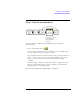
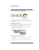
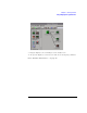
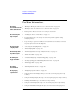
Table Of Contents
- Agilent Technologies 16750A/B Logic Analyzer
- Agilent Technologies 16750A/B Logic Analyzer
- Contents
- Getting Started
- Step 1. Connect the logic analyzer to the device under test
- Step 2. Choose the sampling mode
- Step 3. Format labels for the probed signals
- Step 4. Define the trigger condition
- Step 5. Run the measurement
- Step 6. Display the captured data
- For More Information...
- Example: Timing measurement on counter board
- Example: State measurement on counter board
- Task Guide
- Probing the Device Under Test
- Choosing the Sampling Mode
- To select transitional timing or store qualified
- Formatting Labels for Logic Analyzer Probes
- Setting Up Triggers and Running Measurements
- Displaying Captured Data
- Using Symbols
- Printing/Exporting Captured Data
- Cross-Triggering
- Solving Logic Analysis Problems
- Saving and Loading Logic Analyzer Configurations
- Reference
- The Sampling Tab
- The Format Tab
- Importing Netlist and ASCII Files
- The Trigger Tab
- The Symbols Tab
- Error Messages
- Must assign Pod 1 on the master card to specify actions for flags
- Branch expression is too complex
- Cannot specify range on label with clock bits that span pod pairs
- Counter value checked as an event, but no increment action specified
- Goto action specifies an undefined level
- Maximum of 32 Channels Per Label
- Hardware Initialization Failed
- Must assign another pod pair to specify actions for flags
- No more Edge/Glitch resources available for this pod pair
- No more Pattern resources available for this pod pair
- No Trigger action found in the trace specification
- Slow or Missing Clock
- Timer value checked as an event, but no start action specified
- Trigger function initialization failure
- Trigger inhibited during timing prestore
- Trigger Specification is too complex
- Waiting for Trigger
- Analyzer armed from another module contains no "Arm in from IMB" event
- Specifications and Characteristics
- Concepts
- Understanding Logic Analyzer Triggering
- Understanding State Mode Sampling Positions
- Getting Started
- Glossary
- Index

24
Chapter 1: Getting Started
For More Information...
For More Information...
On making
measurements on the
demo counter board:
• “Example: Timing measurement on counter board” on page 26
• “Example: State measurement on counter board” on page 28
• Making Basic Measurements for a self-paced tutorial
On connecting the
logic analyzer:
• “Probing the Device Under Test” on page 33
• Setup Assistant (see the Setup Assistant help volume) (when using
analysis probes).
• Logic Analysis System and Measurement Modules Installation Guide
for probe pinout and circuit diagrams.
On choosing the
sampling mode:
• “Choosing the Sampling Mode” on page 36
• “The Sampling Tab” on page 115
On formatting labels
for probed signals:
• “Formatting Labels for Logic Analyzer Probes” on page 57
• “The Format Tab” on page 119
On defining the
trigger condition:
• “Understanding Logic Analyzer Triggering” on page 192
• “Setting Up Triggers and Running Measurements” on page 64
• “The Trigger Tab” on page 146
On running
measurements:
• “Running Measurements” on page 86
On displaying
captured data:
• “Displaying Captured Data” on page 88
• Using the Waveform Display Tool (see the Waveform Display Tool help
volume)
• Using the Listing Display Tool (see the Listing Display Tool help volume)
• Working with Markers (see the Markers help volume)
• Using the Chart Display Tool (see the Chart Display Tool help volume)
• Using the Distribution Display Tool (see the Distribution Display Tool