
Technical data

12 SYSTem Subsystem
562 N1911A/1912A P-Series Power Meters Programming Guide
802.11a and HiperLan2
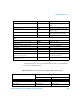
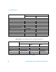
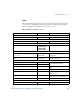
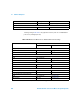
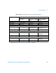
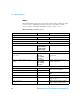
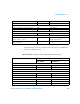
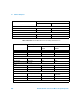
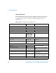
The following table shows the power meter presets when <character_data>
is set to 802DOT11A and HIPERLAN2. Commands not listed are preset
according to their DEFault values (for further information refer to
Table 12- 26).
Tab le 12 - 51 802.11a and HiperLan2: Power Meter Presets
Command Setting Comments
Frequency
[SENS[1]]|SENS2:FREQ[:CW|:FIX] +5200.000 MHz Frequency setting
Sensor measurement mode
[SENS[1]]|SENS2:DET:FUNC NORM Measurement mode
Sensor video bandwidth setup
[SENS[1]]|SENS2:BAND|BWID:VID E9321A/25A: DEF
E9322A/26A: DEF
E9323A/27A: HIGH
N1921/2A: HIGH
Sensor video bandwidth
Gate Setup
[SENS[1]]|SENS2:SWE[1]|2|3|4
:OFF:TIME
Gate 1: 0
Gates 2 - 4: 0
Delay between trigger point and time
gated period.
[SENS[1]]|SENS2:SWE[1]|2|3|4
:TIME
Gate 1: 25 µs
Gates 2 - 4: 0
Length of time gated period for time
gated measurements.
Trigger setup
TRIG[:SEQ[1]|2]:SOUR INT1 Trigger source set up and acquisition
mode continuous triggering
INIT:CONT ON
TRIG[:SEQ]:LEV:AUTO ON Enable automatic setting of the trigger
level
TRIG[:SEQ]:LEV AUTO Power level
TRIG[:SEQ]:SLOP POS Trigger event recognized on the rising
edge of a signal
TRIG[:SEQ]:DEL 0 s Delay between recognition of trigger
event and start of a measurement
TRIG[:SEQ]:HOLD MIN Trigger holdoff
Range
1