
Technical data

SYSTem Subsystem 12
N1911A/1912A P-Series Power Meters Programming Guide 577
NADC
The NADC set- up provides:
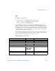
• Average power measurement of both active timeslots in NADC or
IS- 136 “full rate” transmission. This assumes that there are two
timeslots to be measured in each frame as for example with timeslots 0
in the following diagram:
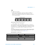
Figure 12-22A Trace Display Of The Active Timeslots
• A trace display of the active timeslots.
The measurement is started by detecting the RF burst—for example the
burst emitted by a mobile—using the internal RF level trigger. The internal
level trigger is set to –20 dBm. Time- gating is used to measure the average
power in two active timeslots which are separated by two inactive
timeslots
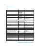
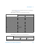
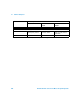
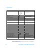
The following table shows the power meter presets when <character_data>
is set to NADC. Commands not listed are preset according to their DEFault
values (for further information refer to Table 12- 26):
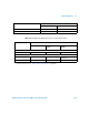
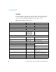
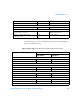
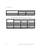
Tab le 12 - 66 NADC: Power Meter Presets
0120
2
1
IS-136 full rate frame
Command Setting Comments
Frequency
[SENS[1]]|SENS2:FREQ[:CW|:FIX] +800.000 MHz Frequency setting
Sensor measurement mode
[SENS[1]]|SENS2:DET:FUNC NORM Measurement mode
Sensor video bandwidth setup