
Technical data

1 Power Meter Remote Operation
38 N1911A/1912A P-Series Power Meters Programming Guide
Setting Offsets
Channel Offsets
The power meter can be configured to compensate for signal loss or gain
in your test setup (for example, to compensate for the loss of a 10 dB
attenuator). You use the SENSe command subsystem to configure the
power meter. Gain and loss correction are a coupled system. This means
that a gain set by [SENSe[1]]|SENSe2:CORRection:GAIN2 is represented
in the [SENSe[1]]|SENSe2:CORRection:LOSS2? command. If you enter an
offset value the state is automatically enabled. However it can be enabled
and disabled using either the
[SENSe[1]]|SENSe2:CORRection:GAIN2:STATe or
[SENSe[1]]|SENSe2:CORRection:LOSS2:STATe commands.
LOSS2 is coupled to GAIN2 by the equation when the default
unit
is linear, and when the default is logarithmic.
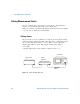
Display Offsets
Display offset values can be entered using the
CALCulate[1|2]:GAIN[:MAGNitude] command.
CALCulate[1|2]:GAIN:STATe must be set to ON to enable the offset
value. If you enter an offset value the state is automatically enabled. This
offset is applied after any math calculations (refer to Figure 1-6 on
page 49).
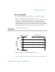
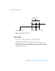
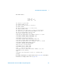
Example
The following example program, in HP Basic, details how to use the
channel and display offsets on an N1912A making a Channel A/B ratio
measurement.
Loss
1
Gain
-------------
=
Gain Loss–=
NOTE
You can only use LOSS2 and GAIN2 for external losses and gains. LOSS1 and GAIN1 are
specifically for calibration factors.