
Technical data
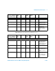
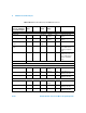

Calibration Factor Block Layout A
N1911A/1912A P-Series Power Meters Programming Guide A-769
1
Corrections are applied in power for E4410 Series, E9300 Series and N8480 Series
sensors (excluding Option CFT).
2
Corrections are applied in voltage versus ADC reading for E9320 Series sensors. This
format also requires only one correction factor across all power levels.
3
The block layout shown for E9320 Series sensors exists in two separate EEPROM
locations. One location contains the calibration factor data for the average path and the
other contains the calibration factor data for the peak path. These EEPROM blocks are
accessed using the SERV:SENS:CALFactor and SERV:SENS:PCALfactor
commands respectively.
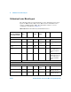
Tab le Si z e:
-
See note
1
The table size is
dependent on the
number of frequency
points.
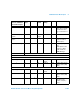
N8480 Series
Sensors: Calibration
Factor Block Layout
No.
Bytes
Contents Data
Format
Data
Range
Units Notes