
Technical data

11
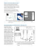
Many power measurement applications do not allow
engineers to sense multiple power points simultaneously
and rather require them to move single sensors from point to
point. This is where the USB signal multiplexer can be used
because it can sequence data from as many as ten channels
of USB data from ten U2000 Series sensors.
The U2000 Series application can be applied on a high-
volume production line where large quantities of wireless
cell phones are measured for output power on test stations
that are located next to each other.
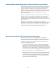
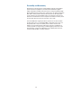
Scalar network analyzers play a
prominent role in microwave
component characterization, such
as refl ection coeffi cient and gain.
However, there may be times when
actual power sensing is much more
preferred. For instance, in power
amplifi er measurements, when the
specifi ed output power is required for
the production specifi cation. In Figure
15, the U2000 Series is used to sample
three power parameters; input power,
refl ected power using a directional
coupler, and amplifi ed output power.
The power data provides for computed
refl ection coeffi cient (return loss),
gain, and a defi nitive, accurate, and
traceable output power. The USB
sensor combination, shown with
associated computations of refl ection
coeffi cient or gain represents a lower
cost solution than a traditional scalar
network analyzer, especially if the
same test component unit requires a
real output power specifi cation test.
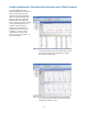
Figure 14 By multiplexing more than ten channels of USB power data with an electronic USB multiplexer,
simultaneous data can be obtained from every sensor point and displayed on the versatile Power
Analysis Manager.
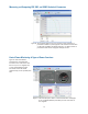
Figure 15 In measurement applications where absolute power data is required,
power sensors can measure the absolute output power for assuring
compliance and also furnish the power data which permits computing
ratios such as return loss and gain, at specifi ed input power
conditions.
Signal Generator
Directional
Coupler
USB
Sensor
R
A
B
Return Loss = A/R
Transmission Loss = B/R
Amplifi er
under test
Multiple-Channel Power Measurements
Computed Parameters from Multiple Sensors’ Measurements