
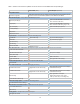
Technical data
19
The wide-dynamic square-law range
of the U2000 Series sensors makes
them ideally suited to measure signal
formats with complex modulation
formats which cause high crest
factors. The principle is that the
peaks of the crest factor spikes do
not exceed the square-law detection
range. Crest factors of ten are
easily handled by assuring that the
measurement range of the sensor is
dialed down in such a way that the
peak power does not exceed +20 dBm.
For users measuring complex power
formats with high crest factors, it is
recommended that they refresh their
background on signal formats on the
use of dual path sensors by referring
to [Ref: 2, pages 29 – 30] [Ref: 2, pages
3 – 6].
Applications that require power
measurements of pulsed RF/
microwave signals (such as radar
signals) are covered in the U2000
Series too, provided that it is permitted
to just measure the average power
of the pulsed modulation waveform.
In many if not most of the system
tests, pulsed power transmitters have
fi xed duty cycle (peak power duration
divided by pulsed repetition period),
thus, an average power reading can be
computed to peak power. Again, for
proper averaging, it must be assured
that the peak pulse power entering
the U2000 Series does not exceed +20
dBm so as not to get out of square-law
range. This may require an external
microwave attenuator pad of 10 dB or
20 dB.
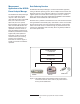
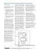
The calibration factor versus frequency
versus temperature characterization is
done once at the factory during
manufacturing to measure each
individual diode stack assembly for
temperature variations. The data that
is run against a frequency response
test forms the basis for the
3-dimensional correction table stored
on-board within the U2000 Series in
the SDRAM and Flashdrive. [Ref: 5]
The test of the stability of the
correction table over several
time periods has resulted in
recommendations that re-calibration
is only required once per year. The
sensor works within a specifi ed
warranty period of one year.
Furthermore, when the yearly
calibration cycle is due, the calibration
facility only needs to make a
frequency response test at laboratory
temperature (25°C). It has been
determined that the temperature
sensitivity profi le stays constant over
time as long as no overload damage
has been experienced. The crucial
point of remote installations of the
U2000 Series is the capability to
perform automatic zeroing without
having to disconnect the RF connector
at the power sensing point, or shut
down the system power. This function
is described as an integrated function
on-board the same microcircuit that
holds the diode stacks, and the signal
switching from high to low sensitivity
channels. [Ref: 5]
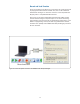
The calibration process may be
performed by returning the U2000
Series to the Agilent Service Facility
or it can be done in the user’s Cal
Lab. Once the new correction data is
obtained, instructions are available to
permit the calibration facility to
input new data tables into the
individual sensor via the USB
communications bus.
Signal Formats
Calibration, Zero and Cal