
Technical data


6
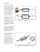
In brief, the input RF/microwave
power drives two measurement
channels, one for the lower level
signals and the other through a
resistive 30 dB attenuator for the high
level channel. At the transition power
point, approximately –10 dBm, the
internal circuitry determines which
channel will provide the output data.
Amplifi cation and signal conditioning
assure that drift and gain stability are
not compromised before hitting the
high performance 14-bit
analog-to-digital converter modules.
From there, the digitized power data
enters the processor which operates
as an on-board computer for the
self-contained sensor.
The processor controls all the
housekeeping details, monitors its
sensor temperature, and provides data
corrections for the frequency
calibration factor. It also determines
which high-low channel to read,
prepares the raw digitized data for
the USB communications bus, and
recieves command information from
the PC or instrument controller. The
processor reacts to the external trigger
signal and maintains corrections for
the analog signal and analog-to-digital
converter offset signals.
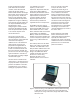
The most obvious controller for the
“Smart Sensor” is the ever-present PC
or laptop. All modern computers have
provisions for USB data connections,
and setting them up is as simple as
hooking up any peripherals to the PC.
It is calibration factor versus
frequency, and also versus
temperature. Temperature within the
power sensing diode bulkhead is
monitored by the thermistor shown in
the block diagram in Figure 6 and this
temperature data is used in the
correction algorithm. The block
diagram in Figure 6 shows two
on-board memory modules that
supplement the basic microprocessor.
The 64 MB synchronous dynamic
random-access-memory (SDRAM) is a
general purpose RAM, used for most
of the variables data such as offset
tables, calibration tables and corrected
power readings. The 4 MB Flash
Memory contains the instrumentation
fi rmware and correction algorithm that
corrects for frequency response of the
sensor, using a 3-dimensional data
matrix.
One of the key features of the U2000
Series is that it does not require daily
calibration. The U2000 Series comes
with pre-written calibration data in the
memory of the sensor. The compact
design of the U2000 Series which
combines all the meter and sensor
electronics in a small casing
eliminates the need to use an
external reference source for sensor
calibration.
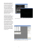
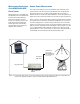
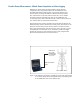
Figure 7 Instant interfacing of the U2000 Series with the Power Panel using
a USB cable can be up to 5 meters long. Signal cable extension
techniques for as long as 90 meters, using a LAN, will be covered
later in this note.
Users can now rely on the yearly
factory or the service center
calibration to remove the gain or
loss of the measurement path which
is now a fi xed loss. The internal
zeroing and calibration-free designs
remove the need for connection and
disconnection of the sensor from the
calibration source. This way, test times
are reduced as well as the degree of
measurement uncertainty and the
wear and tear on the connectors.
The calibration data can be modifi ed
later during its annual visit to the
customer’s Metrology Lab, or back at
the service center.
Another advantage of the U2000
Series is that the devices can be
coupled with other instrumentations,
especially those with internal
microprocessor controls. This allows
standalone instruments to extend their
performance for accurate absolute
power measurements.