
Technical data

6Repair Guide
92 N1911A/1912A P-Series Power Meters Service Guide
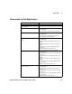
Reassembly Instructions
Instructions Visual
• The reassembly process is simply the
reverse of the disassembly process.
However, there are various points to be
aware of:
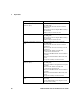
• USB/LAN connectors must rest on top of
the rear panels’ EMC spring fingers.
• The position of the cable clamp depends
on whether option 101 or 003 is fitted.
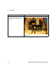
• The main board connector from the PSU
must be pushed firmly to fully engage it.
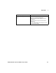
• Take care not to trap any cables when
fitting the top clamshell.
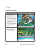
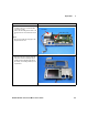
• Analog recorder output connections
(Figure 6-15): Ensure recorder 1 is plugged
into the rear connector. Where applicable,
recorder 2 is plugged into the connector
nearer the front.
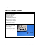
Figure 6-15
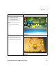
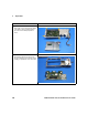
• Sensor flex connections (Figure 6-16):
A – Front, Channel A (for Option 101)
B – Front, Channel B (for Option 101)
C – Rear, Channel A (for Option 003)
D – Rear, Channel B (for Option 003)
Figure 6-16
A
B
C
D