
Technical data

Repair Guide 6
N1911A/1912A P-Series Power Meters Service Guide 93
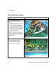
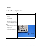
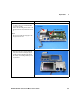
• Sensor RF connections (Figure 6-17):
E – Channel A(+), Black cable
F – Channel A(–), Black/White cable
G – Channel B(+), Black cable
H – Channel B(–), Black/White cable
Note:
• Only connect E and F for N1911A
• Connect E, F, G, H for N1912A
Figure 6-17
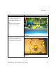
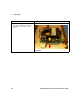
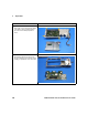
• PSU screw locations (Figure 6-18):
A – Attach PSU to clamshell (6 screws)
B – Attach PSU cable guide (1 screw)
C – Attach PSU safety cover (4 screws)
Figure 6-18
Instructions Visual
E
F
GH
C
A
A
C
B