
Technical data

6Repair Guide
96 N1911A/1912A P-Series Power Meters Service Guide
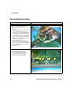
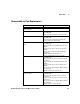
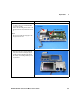
DAP assembly, Channel A (Rear
connectors option)
• Remove handle, bumpers, and top clamshell
(including PSU)
• Disconnect the sensor RF connections from the
main board
• Remove the 4 screws securing the DAP assembly to
the main board
• DAP assembly can now be removed
DAP assembly, Channel B • Remove handle, bumpers, and top clamshell
(including PSU)
• Remove the 4 screws securing the DAP assembly to
the main board
• DAP assembly can now be removed
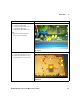
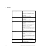
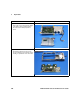
Front panel assembly (front connectors
option)
• Remove handle, bumpers, and top clamshell
(including PSU)
• Disconnect the sensor RF connections from the
main board
• Disconnect the sensor flex connection(s) from the
main board
• Disconnect the calibrator assembly cable
connection from the main board
• Disconnect the EMI earth wires from the calibrator
assembly
• Disconnect main board ribbon cable from the front
panel
• Front panel assembly can now be removed
Front panel assembly (rear
connectors option)
• Remove handle, bumpers, and top clamshell
(including PSU)
• Disconnect calibrator semi-rigid from the rear panel
assembly
• Disconnect the calibrator assembly cable
connection from the main board
• Disconnect the EMI earth wires from the calibrator
assembly
• Disconnect main board ribbon cable from the front
panel
• Front panel assembly can now be removed
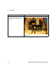
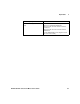
Sensor flex assembly (front connectors
option)
• [Remove front panel assembly as previously
described]
• Use the N1912-61807 special tooling kit to remove
the sensor flex assembly
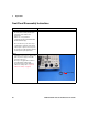
Disassembly of Replacement Part Instructions