
Technical data


Repair Guide 6
N1911A/1912A P-Series Power Meters Service Guide 101
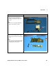
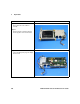
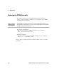
Step 7:
• Remove the 3 screws that attach the
calibrator assembly to the display support
molding, and separate them from one
another
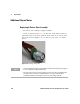
Note:
• Take care not to damage the EMI spring
fingers on the calibrator assembly
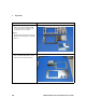
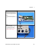
Step 8:
• Disconnect the backlight cable assembly
from the display interface board and inverter
board
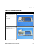
Step 9:
• Remove the 2 screws that attach the display
inter face board to the inverter board, and
separate them from one another
Instructions Visual
EMI Spring
Finger