
Technical data


Repair Guide 6
N1911A/1912A P-Series Power Meters Service Guide 105
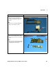
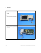
Step 6:
• Attach the inverter board to the display
interface board using the 2 screws removed
earlier
Step 7:
• Connect the inverter board to the display
interface board using the backlight cable
assembly
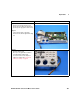
Note:
• The cable must be tucked under the plastic
clip to prevent any fouling
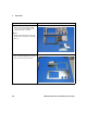
Step 8:
• Attach the calibrator assembly to the display
support molding using the 3 screws removed
earlier
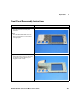
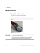
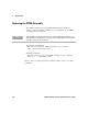
Step 9:
• Carefully spread the EMI fingers outwards,
ensuring they extend beyond the edges of
the hole in which the calibrator assembly is
fitted
Instructions Visual