
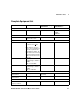
Technical data
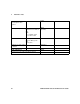

Performance Tests 2
N1911A/1912A P-Series Power Meters Service Guide 29
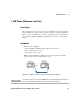
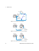
Test Method
1 Enable the path that routes the time base signal to the trigger output
connector.
2 Using the 53132A, measure the frequency of the signal at the trigger
output connector.
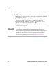
NOTE
• This test can be configured manually via the command SERV:BIST:TBAS:STAT
ON, which enables the 10 MHz feed to the trigger output connector (refer to the
programming guide for further details on the use of this command).
• This test can also be configured manually via the front panel; access the Service menu,
select Self Test, and select Time Base to enable the 10 MHz feed to the trigger output
connector.
• No adjustment is available for this test if it fails (see Chapter 5, “Troubleshooting
Guide”).