
User`s guide


Using N8480 Series Power Sensors 8
N1911A/1912A P-Series Power Meters User’s Guide 215
4 Press to complete the entry.
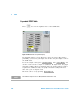
Enter (or edit) the frequency and cal factor pairs as follows:
1 Press to add a new frequency value (or press to edit).
Use the numeric keypad to enter the required value in the Frequency
pop- up window. Complete the entry by pressing the , keys.
2 Enter the new cal factor value (or press to edit). Use the
numeric keypad to enter the required value in the Cal Factor pop- up
window. Complete the entry by pressing the key.
3 Continue adding/editing values until you have entered all the data you
require.
4 When you have finished editing the table press to save the table.
Enter
NOTE
A calibration factor in the range of 1 % to 150 % can be entered.
The following rules apply to naming sensor calibration tables:
• The name must consist of no more than 12 characters.
• All characters must be upper or lower case alphabetic characters, or numeric (0-9), or
an underscore (_).
• No other characters are allowed.
• No spaces are allowed in the name.
Insert
Change
GHz
MHz
Change
%
Done
NOTE
Ensure that the frequency points you use cover the frequency range of the signals you want
to measure. If you measure a signal with a frequency outside the frequency range defined
in the sensor calibration table, the power meter uses the highest or lowest frequency point
in the sensor calibration table to calculate the offset