S Agilent 81101A 50 MHz Pulse Generator Reference Guide S1
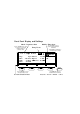
Front Panel Display and Softkeys Mode / Parameter Area Use the CURSOR keys to move the entry focus to a mode, parameter format, or parameter value Use the KNOB to select a mode or modify parameters and formats Entry Focus Press ENTER or a UNIT key to confirm parameter changes Per 1.000µ µs Normal Delay Width LeadE TraiE Modify / Enter Area OFF 1 MODIFY 0ps Offset +0.0mV *OFF 100.0ns Amplit 1.00V ON 5.00ns 50Ω Ω into 50.
Reference Guide Agilent 81101A 50 MHz Pulse Generator Part No. 81101-91021 Printed in Germany March 2000 Edition 1.
Notice Notice Copyright 1998 Agilent Technologies 1998, 2000. All rights reserved. No part of this manual may be reproduced in any form or by any means (including electronic storage and retrieval or translation into a foreign language) without prior agreement and written consent from Agilent Technologies Inc. as governed by United States and international copyright laws. Notice The material contained in this document is subject to change without notice.
Notice Agilent Technologies warrants that its software and firmware designated by Agilent Technologies for use with an instrument will execute its programming instructions when properly installed on that instrument. Agilent Technologies does not warrant that the operation of the instrument software, or firmware, will be uninterrupted or error free.
Safety Summary Safety Summary The following general safety precautions must be observed during all phases of operation of this instrument. Failure to comply with these precautions or with specific warnings elsewhere in this manual violates safety standards of design, manufacture, and intended use of the instrument. Agilent Technologies Inc. assumes no liability for the customer's failure to comply with these requirements.
Safety Summary Ground the Instrument To minimize shock hazard, the instrument chassis and cover must be connected to an electrical protective earth ground. The instrument must be connected to the ac power mains through a grounded power cable, with the ground wire firmly connected to an electrical ground (safety ground) at the power outlet.
Safety Summary Safety Symbols Caution (refer to accompanying documents) Protective earth (ground) terminal In the manuals: WA R NI N G The WARNING sign denotes a hazard. It calls attention to a procedure, practice, or the like, which, if not correctly performed or adhered to, could result in personal injury. Do not proceed beyond a WARNING sign until the indicated conditions are fully understood and met. CA U T IO N The CAUTION sign denotes a hazard.
About this Book About this Book This guide provides reference information primarily for programming the Agilent 81101A via remote control. Chapter 1 “General Programming Aspects” on page 13 gives general hints for programming instruments like the Agilent 81101A using SCPI commands. Chapter 2 “Programming Reference” on page 25 provides detailed information on the SCPI commands supported by the instrument.
About this Book Conventions Used in this Book This book uses certain conventions to indicate elements of the Agilent 81101A’s user interface. The following table shows some examples: Softkeys Press the MODE/TRG softkey to access the Mode/ Trigger screen. Hardkeys Press the MORE key to switch to the alternative softkey layout. Alternate Keys Press SHIFT + 0 (ON/OFF) to switch on the output. The alternate key label—which is selected by pressing the SHIFT key—is given in parentheses.
Contents Notice ......................................................................................... 4 Safety Summary ......................................................................... 6 About this Book ......................................................................... 9 Chapter 1 General Programming Aspects The GP-IB Interface Bus ......................................................... 14 Agilent 81101A Remote Control ............................................
Contents Agilent 81101A Specifications ............................................... 91 General ................................................................................................... 91 Timing Specifications ........................................................................... 93 Level Specifications .............................................................................. 96 Clock Sources ........................................................................................
1 1General Programming Aspects This chapter provides general information on writing GP-IB/SCPI programs for instruments like the Agilent 81101A. Detailed information on programming the Agilent 81101A can be found in Chapter 2 “Programming Reference” on page 25.
General Programming Aspects The GP-IB Interface Bus The GP-IB Interface Bus The General Purpose Interface Bus is the interface used for communication between a controller and an external device, such as the Agilent 81130A. The GPIB conforms to IEEE standard 488-1987, ANSI standard MC 1.1, and IEC recommendation 625-1. If you are not familiar with the GPIB, please refer to the following books: • The Institute of Electrical and Electronic Engineers: IEEE Standard 488.
General Programming Aspects Agilent 81101A Remote Control Agilent 81101A Remote Control GP-IB Address You can only set the GP-IB address from the front panel of the instrument (refer to the Quick Start Guide). The default GP-IB address is 10. Modes of Operation The Agilent 81101A has two modes of operation: • Local The instrument is operated using the front panel keys. • Remote After receiving the first command or query via the GP-IB, the instrument is put into remote state. The front panel is locked.
General Programming Aspects Programming Recommendations Programming Recommendations Here are some recommendations for programming the instrument: • Start programming from the default setting. The common command for setting the default setting is: *RST • Switch off the automatic update of the display to increase the programming speed. The device command for switching off the display is: :DISPlay OFF • The SCPI standard defines a long and a short form of the commands.
General Programming Aspects Programming Recommendations When you have found the correct setting, then use this to create the program. In the program it is recommended to send the command for enabling outputs (for example, :OUTPut ON) as the last command. With this procedure it is possible to switch off the error check system (:SYSTem:CHECk OFF) to increase programming speed. The error check is enabled again by sending *RST.
General Programming Aspects Common Command Summary Common Command Summary This table summarizes the IEEE 488.
General Programming Aspects Status Model Status Model QUESTIONABLE STATUS Voltage Warning Current Warning Timing Warning Frequency Warning 0 1 2 3 4 5 6 7 8 9 15 OPERation Status (NOT USED) 0 1 2 3 4 5 6 7 8 9 Status Byte MAV SRQ 0 1 2 3 4 5 6 7 15 Standard Event Status Operation Complete 0 1 2 Query Error Device Dependent Error 3 Execution Error 4 Command Error 5 6 Power On 7 The instrument has a status reporting system conforming to IEEE 488.2 and SCPI.
General Programming Aspects Status Model Condition Register Transition Filters Event Register Enable Register OR Hardware and Firmware condition 1 0 PTR NTR Summary Bit 1 Latched 0 Condition Register A condition register contains the current status of the hardware and firmware. It is continuously updated and is not latched or buffered. You can only read condition registers. If there is no command to read the condition register of a particular status group, then it is simply invisible to you.
General Programming Aspects Status Model Enable Register The enable register defines which bits in an event register are included in the logical OR into the summary bit. The enable register is logically ANDed with the event register and the resulting bits ORed into the summary bit. Enable registers are read/write, and are not affected by *CLS or querying. Although all status groups have all of these registers, not all status groups actually use all of the registers.
General Programming Aspects Status Model Status Byte The status byte summarizes the information from all other status groups. The summary bit for the status byte actually appears in bit 6 (RQS) of the status byte. When RQS is set it generates an SRQ interrupt to the controller indicating that at least one instrument on the bus requires attention.
General Programming Aspects Status Model OPERation Status Group This Status Group is not used in the instrument.
General Programming Aspects Status Model QUEStionable Status Group Bit QUEStionable 0 Voltage warning 1 Current warning 2 Time warning 3 Unused, always 0 4 Unused, always 0 5 Frequency warning 6 Unused, always 0 7 Unused, always 0 8 Unused, always 0 9 Unused, always 0 10 Unused, always 0 11 Unused, always 0 12 Unused, always 13 Unused, always 0 14 Unused, always 0 15 Always 0 The QUEStionable Status group is used to report warning conditions amongst the voltage, current, p
2 2Programming Reference This chapter provides reference information on the following topics: • “Agilent 81101A SCPI Command Summary” on page 26 • “Default Values, Standard Settings” on page 31 • “Programming the Instrument Trigger Modes” on page 35 • “SCPI Instrument Command List” on page 38 For general programming information, please refer to Chapter 1 “General Programming Aspects” on page 13.
Programming Reference Agilent 81101A SCPI Command Summary Agilent 81101A SCPI Command Summary Command Parameter Description see page (Trigger mode and source) :ARM [:SEQuence[1] | :STARt] [:LAYer[1]] :EWIDTh ON|OFF|1|0 Set/read External Width mode 39 :FREQuency Set/read trigger frequency, when PLL(INT2) used as source 39 :IMPedance Set/read impedance at EXT INPUT 40 :LEVel Set/read threshold level at EXT INPUT 40 :PERiod Set/read trigger period, when PL
Programming Reference Agilent 81101A SCPI Command Summary Command see page Parameter Description OFF|ON|1|0 Set/read normal output state [:INTernal] Set/read internal source impedance of output :EXTernal Set/read expected external load impedance at output 47 NORM|INV Set/read output polarity 48 :OUTPut[1] [:NORMal] [:STATe] 47 :IMPedance :POLarity [:SOURce] :CURRent[1] [:LEVel] [:IMMediate] [:AMPLitude] Set/read channel amplitude current 48 :OFFSet
Programming Reference Agilent 81101A SCPI Command Summary Command Parameter Description OFF|ON Enable/disable double pulses per pulse period see page :DOUBle[1] [:STATe] 59 Set/read delay between double pulses 60 :HOLD TIME|PRATio Hold absolute delay|phase delay fixed with varying frequency 61 :UNIT S|SEC|PCT Set/read delay units 61 WIDTh|DCYCle|TDELay Hold Width|Duty cycle|Trailing edge delay fixed with varying frequency 62 :DELay :HOLD[1] Set/read pulse period 62
Programming Reference Agilent 81101A SCPI Command Summary Parameter Description see page :OFFset Set/read channel offset voltage 71 :HIGH Set/read channel high level voltage 72 :LOW Set/read channel low level voltage 73 [:HIGH] Set/read maximum voltage limit 74 :LOW Set/read minimum voltage limit 74 ON|OFF|1|0 Enable|Disable the voltage limits 75 Read Operation event register 75 :CONDition Numeric Read Operation condition register :ENABle Numeric Set/R
Programming Reference Agilent 81101A SCPI Command Summary Command [:STATe] :SET Parameter Description see page ON|OFF Switch security on and off 82 Block data Set/read complete instrument setting 83 Read SCPI compliance setting 83 :VERSion? :WARNing [:COUNt]? Read number of active warnings 83 :STRing? Read active warnings as concatenated string 84 :BUFFer? Read maximum possible length of concatenated string 84 :TRIGger [:SEQuence [1] | :STARt] (Pulse mode and period source) :COUNt <
Programming Reference Default Values, Standard Settings Default Values, Standard Settings Parameter *RST, Default Values :ARM : EWIDth:STATe OFF :FREQuency 100kHz :IMPedance 50Ω :LEVel +1.00V :PERiod 10.
Programming Reference Default Values, Standard Settings Parameter *RST, Default Values :LOW –10.0mA :STATe OFF :FREQ [:CW|:FIXed] :AUTO 1.00MHz not applicable :HOLD VOLT :PHASe[1][:ADJust] 0.0 :PULSe: :DCYCle[1] 10.0% (derived from Width and Period) :DELay[1] 0.0 :HOLD TIME :UNIT S :DOUBle[1][:STATe] :DELay OFF 250 ns :HOLD TIME :UNIT S :HOLD[1] [:SOURce]:PULSe:PERiod :AUTO WIDTh 1µs not applicable :TDELay[1] 100ns :TRANsition[1|2]:HOLD TIME :UNIT S [:LEADing] 5.
Programming Reference Default Values, Standard Settings Parameter *RST, Default Values [:SOURce]:VOLTage[1] :LEVel] [IMMediate] [:AMPLitude] 1.0V :OFFSet 0.
Programming Reference Default Values, Standard Settings Parameter *RST, Default Values :LEVel 1.
Programming Reference Programming the Instrument Trigger Modes Programming the Instrument Trigger Modes The following figure shows the instrument’s arming/triggering model: :ARM Event detection layer :ARM:SOURce IMMediate (Internal VFO) INTernal2 (Internal PLL) EXTernal (EXT INPUT) Manual (MAN key) :TRIGger Event detection layer :TRIGger:SOURce IMMediate (Internal VFO) INTernal2 (Internal PLL) EXTernal2 (CLK IN) armed? :ARM:SENSe EDGE (Triggered) LEVel (Gated) no yes triggered? no yes generate pul
Programming Reference Programming the Instrument Trigger Modes Use the :ARM subsystem to select the overall triggering mode of the instrument (CONTINUOUS, TRIGGERED, GATED, EXT WIDTH), and the :TRIGger subsystem to select the pulse period source, triggering and number of pulse periods per :ARM event (BURST or PATTERN length). Continuous Set Continuous mode by arming the instrument from its internal oscillator: :ARM:SOURce IMMediate Arm from internal oscillator.
Programming Reference Programming the Instrument Trigger Modes External Width Set External Width mode using the :EWIDth[:STATe] command: :ARM:EWIDth ON Switch on EXT WIDTH mode This command disables the arm-trigger system. The arm-trigger system is reenabled by switching OFF EWIDth mode. Pulses Set Pulses mode by setting the :TRIGger:COUNt to 1 so that a single triggered pulse period is generated for every arm event.
Programming Reference SCPI Instrument Command List SCPI Instrument Command List The following reference sections list the instrument commands in alphabetical order. In addition to a command description, the attributes of each command are described under the following headings. Not all of these attributes are applicable to all commands. The commands are conform to the IEEE 488.2 SCPI standard. Command Shows the short form of the command. Long Shows the long form of the command.
Programming Reference SCPI Instrument Command List Command :ARM:EWID Long :ARM[:SEQuence[1]|STARt][:LAYer]:EWIDth[:STATe] Form Set & Query Parameter ON | OFF | 1 | 0 *RST value OFF Description Use this command to enable the EXT WIDTH trigger mode available on the MODE/TRIGGER SCREEN. When EXT WIDTH mode is switched on, the rest of the :ARM and :TRIG system is disabled. In EXT WIDTH mode a signal applied to the EXT INPUT determines the width and period of the output signal(s) from the instrument.
Programming Reference SCPI Instrument Command List Command :ARM:IMP Long :ARM[:SEQuence[1]|STARt][:LAYer]:IMPedance Form Set & Query Parameter Numeric Parameter Suffix OHM with engineering prefixes, e.g.: MOHM is Megaohms. *RST value 50 Ω Specified Limits 50 Ω or 10 kΩ Description Use this command to program the input impedance of the EXT INPUT connector. Note that only two settings are available. If you try to program any other value, it will be rounded to one of the specified values.
Programming Reference SCPI Instrument Command List Command :ARM:PER Long :ARM[:SEQuence[1]|STARt][:LAYer]:PERiod Form Set & Query Parameter Numeric Parameter Suffix S or SEC with engineering prefixes. *RST value 10.00 µs Specified Limits 20 ns to 999.5 s Description Use this command to program the period of the PLL (INTernal2) when it is used as the :ARM:SOURce for internal triggering of pulses, bursts or patterns.
Programming Reference SCPI Instrument Command List Command :ARM:SENS Long :ARM[:SEQuence[1]|STARt][:LAYer]:SENSe Form Set & Query Parameter EDGE | LEVel *RST value EDGE Description Use this command to select Triggered or Gated mode by choosing whether the instrument arms on the edge(s) or level of the arming signal. When sensing edges, the instrument triggers when the arming signal crosses the selected threshold level (:ARM:LEV) in the selected direction (:ARM:SLOP).
Programming Reference SCPI Instrument Command List Command :ARM:SOUR Long :ARM[:SEQuence[1]|STARt][:LAYer]:SOURce Form Set & Query Parameter IMMediate|INTernal[1]|INTernal2|EXTernal[1]|MANual *RST value IMM Description Use this command to select the triggering mode of the instrument by selecting the source of the arming signal: Triggering Source :ARM:SOURce Mode Internal Osc.
Programming Reference SCPI Instrument Command List Command :MMEM:CAT? Long :MMEMory:CATalog? Form Query Parameter ["A:"] *RST value Not applicable Description Use this command to get a listing of the contents of the currently selected directory on the memory card. As there is only one memory card slot, the parameter A: is optional. The information returned is: ,[,] The total number of bytes used on the memory card.
Programming Reference SCPI Instrument Command List Command :MMEM:COPY Long :MMEMory:COPY Form Event Parameter "filename"[,"A:"],"copyname"[,"A:"] *RST Not applicable Description Use this command to copy an existing file filename in the current directory to a new file copyname. If copyname is the name of a subdirectory in the current directory, a copy of the file filename is made in the sub-directory. Use ".." as copyname to copy a file into the parent directory of the current directory.
Programming Reference SCPI Instrument Command List Command :MMEM:LOAD:STAT Long :MMEMory:LOAD:STATe Form Event Parameter ,"filename"[,"A:"] *RST Not applicable Specified Limits = 0 to 9 (integer) Description Use this command to load a complete instrument setting from file filename in the current directory into memory in the instrument. Memories 1 to 9 are the internal customer memories. Memory 0 holds the default setting. Examples See next command.
Programming Reference SCPI Instrument Command List Command :OUTP[1] Long :OUTPut[1][:NORMal][:STATe] Form Set & Query Parameter ON | OFF | 1 | 0 *RST value OFF Description Use this command to switch the normal OUTPUT on or off. Example To switch on the output: :OUTP ON Command :OUTP[1]:IMP Long :OUTPut[1]:IMPedance[:INTernal] Form Set & Query Parameter Numeric Parameter Suffix OHM with engineering prefixes, e.g.: MOHM is Megaohms.
Programming Reference SCPI Instrument Command List Specified Limits 0.1 Ω to 1 MΩ Description Use this command to set the expected load impedance of the device under test at the OUTPUT connectors. If you have a non-50 Ω load, the output levels at the device under test will not be the levels you program or set via the front panel unless you set the expected load using this command. Example To set the expected load impedance: :OUTP:IMP:EXT 47.6OHM Set load impedance at OUTPUT to 47.
Programming Reference SCPI Instrument Command List Value coupling Amplitude = High – Low High – Low Offset = 2 Range coupling Offset Description Use this command to program the amplitude current of the OUTPUT signal. Note that to set the OUTPUT levels in terms of current, you first have to execute the [:SOURce]:HOLD CURRent command to enable the [:SOURCE]:CURRENT subsystem.
Programming Reference SCPI Instrument Command List Range coupling Amplitude Description Use this command to program the offset current of the OUTPUT signal. Note that to set the OUTPUT levels in terms of current, you first have to execute the [:SOURce]:HOLD CURRent command to enable the :SOURce]:CURRent subsystem.
Programming Reference SCPI Instrument Command List have to execute [:SOURCE]:HOLD CURRent command to enable the [:SOURCE]:CURRent subsystem.
Programming Reference SCPI Instrument Command List • Specified Voltage limits • Actual OUTPUT Impedance setting :OUTPut:IMPedance • Actual Expected Load impedance setting: :OUTPUT:IMPedance:EXTernal Example To program the low level current of the output signal: :HOLD CURR :CURR:LOW 50 MA Enable CURRENT subsystem Set OUTPUT low level to 50 mA Command :CURR[1]:LIM Long [:SOURce]:CURRent[1]:LIMit[:HIGH] Form Set & Query Parameter Numeric Parameter suffix A with engineering prefixes.
Programming Reference SCPI Instrument Command List Command :CURR[1]:LIM:LOW Long [:SOURce]:CURRent[1]:LIMit:LOW Form Set & Query Parameter Numeric Parameter suffix A with engineering prefixes. *RST value –10.0 mA Description Use this command to set/read the low level current limit. If you switch on current limiting, the low level current cannot be set below the programmed limit. The current is not limited by the OUTPUT hardware, this is a software limit.
Programming Reference SCPI Instrument Command List Example To set and activate the current limits for the output: :HOLD CURR :CURR:LIM 50MA :CURR:LIM:LOW –50MA :CURR:LIM:STAT ON Enable CURRENT subsystem Set OUTPUT high level current limit to 50 m Set OUTPUT low level current limit to –50m Switch on OUTPUT limits Command :FREQ Long [:SOURce]:FREQuency[:CW|:FIXed] Form Set & Query Parameter Numeric Parameter Suffix Hz with engineering prefixes, or MHZ for Megahertz.
Programming Reference SCPI Instrument Command List Command :FREQ:AUTO Long [:SOURce]:FREQuency[:CW|:FIXed]:AUTO Form Event Parameter ONCE *RST value Not applicable Description Use this command to measure the frequency at the CLK-IN connector.
Programming Reference SCPI Instrument Command List Command :PHAS[1] Long [:SOURce]:PHASe[1][:ADJust] Form Set & Query Parameter Numeric Parameter suffix DEG or RAD. A parameter without a suffix is interpreted as RAD. Functional coupling Programming the pulse phase also executes [:SOURce]:PULSe:HOLD PHASe so that the pulse phase is held constant when the signal frequency is changed. Value coupling Delay = Phase 360 × Period *RST value 0.
Programming Reference SCPI Instrument Command List Command :PULS:DCYC[1] Long [:SOURce]:PULSe:DCYCle[1] Form Set & Query Parameter Numeric Value coupling Width = Duty Cycle 100 × Period *RST value 10.0% (derived from width and period) Specified limits 0.001% to 99.9%, depends on width, transition & period. Description Use this command to program the duty cycle of the pulse signal. If you want to set an absolute pulse width use [:SOURce]:PULSe:WIDTh[1].
Programming Reference SCPI Instrument Command List Specified limits 0.00 ns to 999 s (limited by period – 20 ns) Description Use this command to set/read the pulse delay. Delay is the time between the start of the pulse period and the start of the leading edge of the pulse. If you want the pulse delay to remain constant when the pulse period is varied (rather than the phase delay) use [:SOURce]:PULSe:DELay[1]:HOLD TIME.
Programming Reference SCPI Instrument Command List Command :PULS:DEL[1]:UNIT Long [:SOURce]:PULSe:DELay[1]:UNIT Form Set & Query Parameter S | SEC | PCT | DEG | RAD *RST value S Description Use this command to set/read the default units for the pulse delay parameter. The default unit of a parameter is the unit used when the parameter is programmed to a value without a unit suffix.
Programming Reference SCPI Instrument Command List Command :PULS:DOUB[1]:DEL Long [:SOURce]:PULSe:DOUBle[1]:DELay Form Set & Query Parameter Numeric Parameter suffix S with engineering prefixes. You can change the default unit using [:SOURce]:PULSe:DOUBle:DELay[1]:UNIT. Value coupling DblDel% = DblDel Period × 100 *RST value 0.0 Specified limits 10 ns to 999.5 s (width +10 ns) to (period – width – 10 ns) min.
Programming Reference SCPI Instrument Command List Command :PULS:DOUB[1]:DEL:HOLD Long [:SOURce]:PULSe:DOUBle[1]:DELay:HOLD Form Set & Query Parameter TIME|PRATio *RST value TIME Description Use this command to set/read the coupling between the pulse period and the double-pulse delay: Example TIME The absolute double-pulse delay is held fixed when the pulse period is varied. PRATio The double-pulse delay as percentage of period is held fixed when the pulse period is varied.
Programming Reference SCPI Instrument Command List Command :PULS:HOLD[1] Long [:SOURce]:PULSe:HOLD[1] Form Set & Query Parameter WIDTh | DCYCle | TDELay *RST value WIDTh Description Use this command to set whether the pulse width, the pulse duty cycle or the pulse trailing edge delay is held constant when the pulse period is changed.
Programming Reference SCPI Instrument Command List You cannot set the pulse period if you have selected the CLK-IN connector as the frequency source (:TRIG:SOUR EXT). Example To set the pulse period using the internal oscillator: :TRIG:SOUR INT :PULS:PER 25NS Select internal osc.
Programming Reference SCPI Instrument Command List Example To program the pulse width by means of the delay parameters: Set OUTPUT delay to 500 ns Hold OUTPUT delay constant with varying period Set OUTPUT trailing delay to 750 ns :PULS:DEL 500NS :PULS:DEL:HOLD TIME :PULS:TDEL 750NS Command :PULS:TRAN[1]:HOLD Long [:SOURce]:PULSe:TRANsition[1]:HOLD Form Set & Query Parameter TIME | WRATio *RST value TIME Description Use this command to set the coupling between transition times and the pulse wid
Programming Reference SCPI Instrument Command List Command :PULS:TRAN[1]:UNIT Long [:SOURce]:PULSe:TRANsition[1]:UNIT Form Set & Query Parameter S | SEC | PCT *RST value S Description Use this command to set the default units for the pulse transition times. The default unit is used when the parameter is programmed to a value without a unit suffix.
Programming Reference SCPI Instrument Command List Command :PULS:TRAN[1]:TRA Long [:SOURce]:PULSe:TRANsition[1]:TRAiling Form Set & Query Parameter Numeric Parameter suffix S with engineering prefixes, or PCT *RST value 5 ns Specified limits 5 ns to 200 ms Parameter coupling By default: Trailing edge = Leading edge with :PULS:TRAN:TRA:AUTO ON. Use :PULS:TRAN:TRA:AUTO OFF to enable independent programming of the trailing edge within a 1:20 ratio for the ranges.
Programming Reference SCPI Instrument Command List Command :PULS:TRAN[1]:TRA:AUTO Long :[SOURce]:PULSe:TRANsition[1]:TRAiling:AUTO Form Set & Query Parameter ON|OFF|ONCE *RST value ON Description Use this command to set/read the automatic coupling of the pulse trailing edge transition time to the leading edge transition time.
Programming Reference SCPI Instrument Command List Command :PULS:WIDT[1] Long [:SOURce]:PULSe:WIDTh[1] Form Set & Query Parameter Numeric Parameter suffix S with engineering prefixes *RST value 100 ns Specified limits 10 ns to 999.5 s (max. period –10 ns) Description Use this command to program the width of the pulse signal. If you want to set width as duty cycle use [:SOURce]:PULSe:DCYCle[1].
Programming Reference SCPI Instrument Command List Example To set up the external PLL reference: :ROSC:SOUR EXT :ROSC:EXT:FREQ 10 MHZ Set external PLL reference (CLK-IN) Set expected PLL reference frequency to 10 MHz Command :ROSC:EXT:FREQ Long [:SOURce]:ROSCillator:EXTernal:FREQuency Form Set & Query Parameter Numeric *RST value 5 MHz Specified limits 5 MHz or 10 MHz Description Use this command to set/read the expected reference frequency for the PLL at the CLK-IN connector.
Programming Reference SCPI Instrument Command List Command :VOLT[1] Long [:SOURce]:VOLTage[1][:LEVel][:IMMediate][:AMPLitude] Form Set & Query Parameter Numeric Parameter suffix V with engineering prefixes. Value coupling High = Offset + Amplitude Low = Offset – 2 Amplitude 2 Range coupling With Offset, see page 71 *RST value 1.00 V Specified limits 100 mVpp to 10.
Programming Reference SCPI Instrument Command List Command :VOLT[1]:OFFSet Long [:SOURce]:VOLTage[1][:LEVel][:IMMediate]:OFFSet Form Set & Query Parameter Numeric Parameter suffix V with engineering prefixes. Value coupling High = Offset + Amplitude 2 Low = Offset – Amplitude 2 Range coupling With Amplitude, see page 70 *RST value 0.0 mV Specified Limits –10 V to +10 V Description Use this command to program the offset voltage of the OUTPUT signal.
Programming Reference SCPI Instrument Command List Command :VOLT[1]:HIGH Long [:SOURce]:VOLTage[1][:LEVel][:IMMediate]:HIGH Form Set & Query Parameter Numeric Parameter suffix V with engineering prefixes. Value coupling Amplitude = High – Low High – Low Offset = 2 Range coupling With low level, see page 73 *RST value 500 mV Specified limits –9.9 V to 10.0 V (50 Ω into 50 Ω) Description Use this command to program the high level voltage of the OUTPUT signal.
Programming Reference SCPI Instrument Command List Command :VOLT[1]:LOW Long [:SOURce]:VOLTage[1][:LEVel][:IMMediate]:LOW Form Set & Query Parameter Numeric Parameter suffix V with engineering prefixes. Value coupling Amplitude = High – Low Offset = High–Low 2 Range coupling With high level, see page 72 *RST value –500 mV Specified limits –10.0 V to 9.9 V (50 Ω into 50 Ω) Description Use this command to program the low level voltage of the OUTPUT signal.
Programming Reference SCPI Instrument Command List Command :VOLT[1]:LIM Long [:SOURce]:VOLTage[1]:LIMit[:HIGH] Form Set & Query Parameter Numeric Parameter suffix V with engineering prefixes. *RST value +500 mV Description Use this command to set/read the high level voltage limit. If you switch on voltage limiting, the high level voltage cannot be set above the programmed limit. Note that the voltage is not limited by the OUTPUT hardware, this is a software limit.
Programming Reference SCPI Instrument Command List Command :VOLT[1]:LIM:STAT Long [:SOURce]:VOLTage[1]:LIMit:STATe Form Set & Query Parameter ON | OFF | 1 | 0 *RST value OFF Description Use this command to switch the output limits on or off. When you switch on the output limits, you cannot program the output levels beyond the programmed limits, until you switch off the voltage limits. The limits apply whether you program high/low levels or amplitude/offset levels.
Programming Reference SCPI Instrument Command List Command :STATus:PRESet Long :STATus:PRESet Form Event *RST value Not Applicable Description This command • Clears all status group event registers • Clears the error queue • Presets the status group enable-, PTR-, and NTR-registers as follows: Status Group Register Preset value OPERation ENABle 0000000000000000 PTR 0111111111111111 NTR 0000000000000000 ENABle 0000000000000000 PTR 0111111111111111 NTR 0000000000000000 QUEStionable C
Programming Reference SCPI Instrument Command List 1. :STATus:QUEStionable[:EVENt]? Form *RST value Description Query Not Applicable This command reads the event register in the QUEStionable status group. 2. :STATus:QUEStionable:CONDition? Form *RST value Description Query Not Applicable This command reads the condition register in the QUEStionable status group. 3.
Programming Reference SCPI Instrument Command List Command :SYST:CHEC Long :SYSTem:CHECk[:ALL][:STATe] Form Set & Query Parameter OFF | ON *RST value ON Description Use this command to switch the instrument’s error checking on or off. Switch off the error checking if you want to improve the programming speed of the instrument, but remember that no invalid parameter or mode settings will be detected and reported.
Programming Reference SCPI Instrument Command List The above message is an example of a customized description. Generic descriptions are available in the SCPI 1995 Command Reference, items 21.8.4 to 21.8.11. For more detailed information in the 81110A error. Send ":SYST:WARN:STR?". Alternatively, the HELP key shows the current errors and warnings and their description on the instruments display.
Programming Reference SCPI Instrument Command List Description No. Key Description 11 DATA ENTRY +/ 12 Cursor Up 13 Cursor Down 14 Cursor Left 15 Cursor Right 16 MAN 17 STORE 18 HELP 19 SHIFT 20 MORE 21 Softkey 1 22 Softkey 2 23 Softkey 3 24 Softkey 4 25 NANO 26 MICRO/MEGA 27 MILLI/KILO 28 ENTER 29 Modify Knob Left (counter-clockwise) 30 Modify Knob Right (clockwise) In query form, this command reads the last key pressed.
Programming Reference SCPI Instrument Command List • In remote mode only the softkeys below the display and the SHIFT (LOCAL) key are active. Because the instrument normally switches to remote mode when any command is received, including :SYSTem:KEY, simulating one of the other disabled keys has no effect. • If you want to simulate full front panel operation, you must prevent the instrument from entering remote mode by using the REN line of the GP-IB to maintain local mode (LOCAL 7 in BASIC).
Programming Reference SCPI Instrument Command List Command :SYST:SEC Long :SYSTem:SECurity[:STATe] Form Set & Query Parameter ON|OFF *RST value OFF Description CA U T IO N Do not switch on system security unless you are willing to erase the instrument settings stored in the instrument.
Programming Reference SCPI Instrument Command List Command :SYST:SET Long :SYSTem:SET Form Set & Query Parameter Block data *RST value Not applicable Description In query form, the command reads a block of data containing the instrument’s complete setup.
Programming Reference SCPI Instrument Command List Command :SYST:WARN:STR? Long :SYSTem:WARNing:STRing? Form Query *RST value Not applicable Description Use this command to read all the currently active warning messages. The warning messages are concatenated to form a single string with a “;” as separator between the messages.
Programming Reference SCPI Instrument Command List Examples To set up a triggered burst of 16 Single Pulses at Out1, each burst triggered by a positive edge at the EXT INPUT: :ARM:SOUR EXT1 :ARM:SENS EDGE :ARM:SLOP POS :TRIG:COUN 16 :TRIG:SOUR INT1 :DIG:PATT OFF :PULS:DOUB OFF Set arming from EXT INPUT Set arming on edges Set arming on positive edges Burst length 16 Pulse period trigger from internal osc.
Programming Reference SCPI Instrument Command List Command :TRIG:LEV Long :TRIGger:LEVel Form Set & Query Parameter Numeric Parameter Suffix V with engineering prefixes. *RST value 1.0 V Specified Limits –10 V to +10 V Description Use this command to program the triggering threshold of the CLK-IN connector. Example To set the input impedance and the threshold of the CLK-IN connector: :TRIG:IMP 50OHM :TRIG:LEV 2.5V :TRIG:SOUR EXT2 Set CLK-IN impedance to 50 Ω Set CLK-IN threshold to 2.
Programming Reference SCPI Instrument Command List Pulse period sources set by :TRIG:SOUR Pulse period source :TRIG:SOURce internal osc internal PLL CLK-IN IMMediate INTernal2 EXTernal2 INTernal[1] 87
Programming Reference SCPI Instrument Command List 88
3 3Specifications In this chapter you will find the specifications of the Agilent 81101A Pulse Generator. At the end of this chapter, “Pulse Parameter Definitions” on page 105 provides detailed information on the definition of the pulse parameters used by the instrument. NOTE Warranted Performance Specifications describe the instrument’s warranted performance. Nonwarranted values are described as typical.
Specifications Declaration of Conformity Declaration of Conformity Manufacturer Agilent Technologies Deutschland GmbH Boeblingen Verification Solutions Herrenberger Str.
Specifications Agilent 81101A Specifications Agilent 81101A Specifications General Environmental Conditions Operating temperature: 0 °C to +55 °C Storage temperature: –40 °C to +70 °C Humidity: 95% r.h.
Specifications Agilent 81101A Specifications Weight Net 8.5 kg Single Channel 9.2 kg Dual Channel Shipping 13.8 kg Dual Channel Recalibration period 1 year recommended Warranty 3 years standard Acoustic Noise Emission For ambient temperature up to 30°C, under normal operation and at the typical operator position: LpA = 52 dB (5.9 bel) typical {47 dB (5.3 bel) at 23°C) typical} Measured in accordance with ISO 7779/EN 27779.
Specifications Agilent 81101A Specifications Timing Specifications Period Period can also be entered as frequency. Period Agilent 81101A Range: 20 ns to 999.5 s Resolution: 3.5 digits, 5 ps best case for VFO 4 digits, 1 ps best case for PLL Accuracy: PLL: ±0.01% VFO: ±5% Repeatability: typically 4 times better than accuracy RMS-jitter: PLL: 0.001% + 15 ps VFO: 0.01% + 15 ps Frequency range: 1.
Specifications Agilent 81101A Specifications Width Can be entered as absolute width, duty cycle or trailing edge delay. Width Agilent 81101A Range: 10 ns to 999.5 s (max value: period –10 ns) Accuracy: ±5 % ±250 ps Duty cycle: 0.1% to 95% (depends on period and width; overprogrammable to 99%) Duty cycle values from 0.1% to 95% can be entered directly. For values >95 % press SHIFT and use the Modify knob. Note that pulses may be deteriorated or skipped due to the inaccuracy of period and width.
Specifications Agilent 81101A Specifications Double Pulse Delay Double pulse delay and delay are mutually exclusive. Double Pulse delay is the delay between the two pulses in Double Pulse mode. Double Pulse Delay Agilent 81101A Double Pulse Delay range: 20 ns to 999.5 s (width + 10 ns) to (period – width – 10 ns) Accuracy: ±5 % ±500 ps Min. period: 40 ns (25 MHz) Transition Times Measured between 10% and 90% of amplitude. Can be entered as leading/ trailing edge or % of width.
Specifications Agilent 81101A Specifications Leading and trailing edges can be programmed independently within the following ranges (Maximum ratio 1:20): 5ns Level Specifications Level Parameters Agilent 81101A Source impedance: selectable 50 Ω ± 1% typical or 1 kΩ Maximum external voltage: ±24 V Short circuit current: ±400 mA Normal/complement: selectable ON/OFF: relay connect/disconnect output (HiZ).
Specifications Agilent 81101A Specifications Level Parameters Level parameters can be entered as high/low level in terms of voltage or current or offset/amplitude. Level Specifications (50Ω into 50Ω) (1kΩ into 50Ω) Amplitude: 100 mVpp to 10.0 Vpp 200 mVpp to 20.0 Vpp Level Window –10.0 V to +10.0 V –20.0 V to + 20.
Specifications Agilent 81101A Specifications Clock / PLL Reference Input Input Specifications Agilent 81101A Input impedance: 50Ω or 10kΩ selectable Threshold: –10 V to +10 V Maximum input voltage: +15 V Input transitions: <100 ns Input Frequency: dc to max 50 MHz Minimum pulse width: 10 ns Input sensitivity: < 300 mVpp typical Delay from Clock Input to TRIGGER OUT/ STROBE OUT: 12 ns typical Rear panel BNC connector used as: • External system clock input: pulse frequency = input frequency
Specifications Agilent 81101A Specifications External Clock • The output period is determined by the signal at clock input. Frequency accuracy can be increased by using a precise external clock. • Trigger synchronously to external clock: the output period is synchronous to the signal at clock input. The signal at the External Input is used for arming. Output Modes Pulses Mode The output signal consists of single or double pulses, controlled by the Trigger mode.
Specifications Agilent 81101A Specifications Trigger Modes Continuous Generate continuous pulses, double pulses, or bursts. Externally Triggered Each active input transition (rising, falling or both) triggers a single pulse, a double pulse, or a burst. The trigger source can be selected from: • External Input • MAN Trigger key • internal PLL. Externally Gated The active input level (high or low) enables pulses, double pulses, or bursts. The last pulse, double pulse, or burst is always completed.
Specifications Agilent 81101A Specifications Trigger and Strobe Specifications Trigger Output Trigger Output Specifications Agilent 81101A Level: TTL or ECL selectable Output impedance: 50 Ω typical Trigger pulse width: typically 50% of period Triggered mode: 9 ns typically External Width mode: recovered pulse shape of external signal Maximum external voltage: –2 V ...
Specifications Agilent 81101A Specifications Typical Delays Mode from to typ. value External Width Ext Input Strobe/Trigger Out OUTPUT 8.5 ns 22.5 ns Trigger Gated Ext Input Strobe/Trigger Out OUTPUT 12.0 ns 29.0 ns Continuous Strobe/ Trigger Out OUTPUT 17.0 ns Ext. clock signal as pulse period CLK-IN Strobe/Trigger Out OUTPUT 12.0 ns 29.
Specifications Agilent 81101A Specifications Human Interface Overprogramming Parameter values can be entered exceeding the specified range. Warnings and Errors Warning messages indicate potentially conflicting parameters due to accuracy tolerances. Error messages indicate conflicting parameters. Help Key Displays a context-sensitive message about the selected parameter. Concept help for getting started is also available.
Specifications Agilent 81101A Specifications Remote Control Operates according to IEEE standard 488.2, 1987 and SCPI 1992.0. Function Code SH1, AH1, T6, L4, SR1, RL1, PP0, DC1, DT1,C0. Programming Times (all checks and display off). Command Typical execution time One parameter or mode 30 ms typ.
Specifications Pulse Parameter Definitions Pulse Parameter Definitions Here you find the pulse parameter definitions of terms used in the instrument specifications.
Specifications Pulse Parameter Definitions Time Reference Point The time reference point is at the median of the amplitude (50% amplitude point on pulse edge): 100% 50% Median 0% Pulse Period The time interval between the leading edge medians of consecutive output pulses: 50% Pulse Period Trigger Delay Interval between trigger point of the external trigger input signal and the trigger output pulse’s leading edge median.
Specifications Pulse Parameter Definitions practice, start points may shift with changes in transition time) when transition times are varied. This is more convenient for programming and the width display is easy to interpret. Pulse Delay Interval between leading edge medians of trigger output pulse and output pulse: Trigger Output Output Signal Fixed Delay Variable Delay The specified and displayed value is that obtained with the fastest leading edge.
Specifications Pulse Parameter Definitions Transition Time Interval between the 10% and 90% amplitude points on the leading/ trailing edge: 100 % 90 % Amplitude Transition Time 10 % Amplitude 0% Linearity Peak deviation of an edge from a straight line through the 10% and 90% amplitude points, expressed as percentage of pulse amplitude: 100 % Amplitude 90 % Amplitude Deviation 10 % Amplitude 0 % Amplitude 108
Specifications Pulse Parameter Definitions Jitter Short-term instability of one edge relative to a reference edge. Usually specified as rms value, which is one standard deviation or “sigma”. If distribution is assumed Gaussian, six sigma represents 99.74% of the peak-peak jitter. The reference edge for period jitter is the previous leading edge. That for delay jitter is the leading edge of the trigger output. Width jitter is the stability of the trailing edge with regard to the leading edge.
Specifications Pulse Parameter Definitions Preshoot, Overshoot, Ringing Preshoot and overshoot are peak distortions preceding/following an edge. Ringing is the positive-peak and negative-peak distortion, excluding overshoot, on pulse top or base. For example, a combined preshoot, overshoot, and ringing specification of 5% implies: • Overshoot/undershoot < 5% • Largest pulse-top oscillation <+ 5%, of pulse amplitude.
Specifications Pulse Parameter Definitions Repeatability When an instrument operates under the same environmental conditions and with the same settings, the value of a parameter will lie within a band inside the accuracy window. Repeatability defines the width of this band.
Specifications Pulse Parameter Definitions 112
Index Symbols % of Per 57, 58 A Acoustic Noise Emission 92 Amplitude current 48 definition 109 voltage 70 B Burst length 84 mode 84 C Certification met specifications 5 Clear Error Queue 76 Clear Status 76 CLK-IN impedance 85 slope 86 threshold 86 Command List 26 Common Commands 18 Condition Register 20 Continuous Mode 43 Current Limits 53 D DblDel 60, 61 Declaration of Conformity 90 Default Units 61 Default units 58 Definition double pulse 107 interchannel delay 107 jitter 109 Linearity 108 pulse delay 107
Index J Jitter definition 109 K Key-Code Reference 80 L Last Key Pressed 79 Leading Edge command 65 definition 108 Linearity definition 108 List of Commands 26 Load File into memory ’n’ 46 Load Impedance 47 Low Level current 51 current limit 53 definition 109 voltage 73 voltage limit 74 M Memory Card catalog/DIR 44 change directory 44 copy file 45 delete file 45 format 45 initialize 45 load from 45 store to 46 O Offset current 49 definition 109 voltage 71 Operation Status 23 Output complement 48 impedance 4
Index S Safety symbols 8 SCPI Command Dictionary 38 Version 83 Setting load into memory ’n’ 46 Settling Time definition 110 Simulating Key Presses 79 Skew definition 107 Specifications 89 CLK-IN 98 delay 94 double pulse delay 95 external clock 99 general 91 memory card 103 output modes 99 Period 93 PLL 98 PLL REF 98 pulse performance 97 pulse width 94 remote control 104 strobe output 101 timing 93 timing (PLL) 98 transition times 95 trigger modes 100 trigger output 101 Stability definition 109 Standard Even
Index 116
Front Panel Controls DATA ENTRY MAN 7 RECALL PERIOD STORE 4 AUTOSET HELP 8 DELAY 5 9 CURSOR/ DIGIT MODIFY nano WIDTH 6 HIGH micro Mega LEAD TRAIL 1 2 3 milli kilo LOW .
Copyright Agilent Technologies 1998, 2000 Edition E0300 Printed in Germany 81101-91021
MANUAL CHANGES Manual for Model Number Manual printed on Manual Part Number September, 01 81101A März 2000 E0300 81101-91021 Make all ERRATA corrections.
MODEL 81101A ____________________________________________________________________ ERRATA Page 91, Power consumption: 170VA max. Page 92, Specifications change to read: Recalibration period 3 years recommended Page 93, Timing Specifications add: Common Specifications The following specifications apply to all timing parameters unless otherwise specified in the following. Repeatability: typically 4 times better than accuracy Resolution: 3.5 digits, best case 5 ps RMS Jitter: 0.
MODEL 81101A ____________________________________________________________________ INDEX OF MANUAL CHANGE MANUAL CHANGE ERRATA 1 FRAME See attached Declaration of Conformity __________________________________________________________________________________ 05.09.
MODEL 81101A ____________________________________________________________________ MANUAL CHANGE 1 On page 90, Specifications change to read: See attached Declarations of Conformity __________________________________________________________________________________ 05.09.
DECLARATION OF CONFORMITY According to ISO/IEC Guide 22 and CEN/CENELEC EN 45014 Manufacturer’s Name: Manufacturer’s Address: Agilent Technologies Deutschland GmbH Boeblingen Verifications Solutions (BVS) Herrenberger Str.