
User`s guide


User’s and Service Guide 6-21
Service
Troubleshooting and Block Diagram
Troubleshooting and Block Diagram
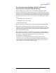
This section contains information on troubleshooting the test set to the
assembly level only. By following these procedures you should be able to
determine whether the power supply, front panel, or main switch board
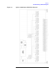
needs replacing. A block diagram is included at the end of this section
as an aid in troubleshooting.
Theory of operation information can be found in the next section of this
manual.
General Troubleshooting Notes
WARNING Always turn the instrument power off before removing or
installing an assembly.
CAUTION If you need to disassemble the instrument, be sure to work at an
antistatic workstation and use a grounded wrist strap to prevent
damage from electrostatic discharge (ESD). See Figure 1-3 on page 1-7.
Troubleshooting Power Supply Problems
Turn the instrument on. Check the condition of the LCD on the front
panel:
Step 1. If the LCD is off, check the main fuse located in the power supply filter
at the rear of the instrument and replace if necessary.
Step 2. If the LCD is still off, there is still a possibility that the power supply is
not supplying the necessary +24V, +12V, and +5V to the main board.
Step 3. If the LCD is still off, check the cable between the main board and front
panel board.
Step 4. Finally, disconnect the DC power cable from the power supply to the
main switch board and measure the voltages. They should be +24V,
+12V, and +5V. If not, replace the power supply.