
User`s guide


User’s and Service Guide 6-25
Service
Theory of Operation
A3 Controller Board (Mother Board) and Switch
Driver Board (Daughter Board) Theory
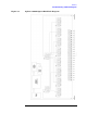
Refer to Figure 6-1 on page 6-23 for the following discussion. The
mother and daughter board provide the bias to switch the paths of the
various ports to the Transmission and Reflection ports. The front panel
display contains an LCD that indicates the switched ports. A particular
test port (1 through 24) can be in one of three states. The three states
are:
• Switched to the forward path
• Switched to the reverse path
• Terminated in 50 Ω
When a port is not connected, it is automatically terminated in 50 Ω.
The test set consists of twenty-four (24) 1x2 switches, eight (8) 1x6
switches, and two (2) 1x4 switches. The 1x2 switches divide each of the
input ports (1 through 24) into two separate paths, the Transmission
path or the Reflection path.
Each path, Transmission or Reflection, is routed to a bank of four (4)
1x6 switches, for a total of eight (8) 1x6 switches. Each bank of switches
is routed to a single 1x4 switch where it becomes either the
Transmission or Reflection port.
All switches are mechanical, biased according to the necessary
switching path. A user interface through the GPIB and parallel ports
converts the necessary input signals from the user to the necessary
control signals to control the switching paths.