
User`s guide


2-12
Making Mixer Measurements (Option 089 Only)
Measurement Considerations
5. Measure the output power in the R channel by pressing:
Observe the 13 to 16 dB offset in measured power. The actual input power level to the R
channel input must be 0 dBm or less, −10 dBm typical, to avoid receiver saturation
effects. The minimum signal level must be greater than −35 dBm to provide sufficient
signal for operation of the phaselock loop.
6. You cannot trust R channel power settings without knowing about the offset involved.
Perform a receiver calibration to remove any power offsets by pressing:
Once completed, the R channel should display the reference power (−10 dBm in this
example).
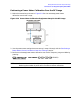
Power Meter Calibration
Mixer transmission measurements are generally configured as follows:
measured output power (Watts) / set input power (Watts)
OR
measured output power (dBm) − set input power (dBm)
For this reason, the set input power must be accurately controlled in order to ensure
measurement accuracy.
The amplitude variation of the analyzer is specified at ±1 dB over any given source
frequency. This may give a maximum 2 dB error for a mixer transmission test setup: ±1dB
for the source over the IF range during measurement and ±1 dB over the RF range during
measurement.
Higher measurement accuracy may be obtained through the use of power meter
calibration. You can use power meter calibration to correct for power offsets, losses, and
flatness variations occurring between the analyzer source and the input to the mixer
under test. Refer to the power meter documentation for its calibration procedures.
Meas
INPUT PORTS
R
Cal
RECEIVER CAL
−10 x1
TAKE RCVR CAL SWEEP