
User`s guide


3-36
Making Time Domain Measurements
Gating
Setting the Gate
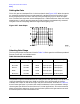
Think of a gate as a bandpass filter in the time domain (see Figure 3-27). When the gate is
on, responses outside the gate are mathematically removed from the time domain trace.
Enter the gate position as a start and stop time (not frequency) or as a center and span
time. The start and stop times are the bandpass filter −6 dB cutoff times. Gates can have a
negative span, in which case the responses inside the gate are mathematically removed.
The gate's start and stop flags define the region where gating is on.
Figure 3-27 Gate Shape
Selecting Gate Shape
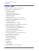
The four gate shapes available are listed in Table 3-4. Each gate has a different passband
flatness, cutoff rate, and sidelobe levels.
The passband ripple and sidelobe levels are descriptive of the gate shape. The cutoff time
is the time between the stop time (−6 dB on the filter skirt) and the peak of the first
sidelobe, and is equal on the left and right side skirts of the filter. As shown in Table 3-4,
the minimum gate span is just twice the cutoff time because it has no passband. Always
choose a gate span wider than the minimum. For most applications, do not be concerned
about the minimum gate span, simply use the knob to position the gate markers around
the desired portion of the time domain trace.
Table 3-4 Gate Characteristics
Gate Shape Passband Ripple Sidelobe Levels Cutoff Time Minimum Gate Span
Gate Span
Minimum ±0.10 dB −48 dB 1.4/Freq Span 2.8/Freq Span
Normal ±0.10 dB −68 dB 2.8/Freq Span 5.6/Freq Span
Wide ±0.10 dB −57 dB 4.4/Freq Span 8.8/Freq Span
Maximum ±0.10 dB −70 dB 12.7/Freq Span 25.4/Freq Span
Note: With 1601 frequency points, gating is available only in the bandpass mode.