
User`s guide


6-43
Calibrating for Increased Measurement Accuracy
Calibrating for Noninsertable Devices
6. Save the results to disk. Name the file "PORT2."
7. Determine the electrical delay of adapter A3 by performing steps 1 through 7 of "Modify
the Cal Kit Thru Definition" on page 6-46.
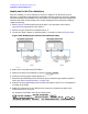
Remove the Adapter
When the two sets of error correction files have been created (now referred to as "cal sets"),
the adapter may be removed.
8. Press . This brings up the following menu:
• (This provides a quick reference guide to using the
adapter removal technique.)
•
•
•
•
•
9. Press to bring up the following two choices:
•
•
also brings up the internal (or external if internal not used) disk
file directory.
NOTE In the following two steps, calibration data is recalled, not instrument states.
10.From the disk directory, choose the file associated with the port 1 error correction, then
press .
11.When this is complete, choose the file for the port 2 error correction and press
.
12.When complete, press .
13.Enter the value of the electrical delay of adapter A3.
Press and enter the value.
14.Select the appropriate key: or .
15.Press to complete the technique for calculating the new error
coefficients and overwrite the current active calibration set in use.
This process uses up an internal memory register. The calibration in this register is not
the calibration created by adapter removal, rather it is a "scratch" calibration. You may
wish to delete the register, or re-save the new calibration in this register as shown in
the following step.
Cal
MORE
ADAPTER REMOVAL
HELP ADAPT REMOVAL
RECALL CAL SETS
ADAPTER DELAY
ADAPTER COAX
ADAPTER WAVEGUIDE
REMOVE ADAPTER
RECALL CAL SETS
RECALL CAL PORT 1
RECALL CAL PORT 2
RECALL CAL SETS
RECALL CAL PORT 1
RECALL CAL PORT 2
RETURN
ADAPTER DELAY
ADAPTER COAX
ADAPTER WAVEGUIDE
REMOVE ADAPTER