
User`s guide


7-41
Operating Concepts
Measurement Calibration
Characterizing Microwave Systematic Errors
One-Port Error Model
In a measurement of the reflection coefficient (magnitude and phase) of a test device, the
measured data differs from the actual, no matter how carefully the measurement is made.
Directivity, source match, and reflection signal path frequency response (tracking) are the
major sources of error. See Figure 7-24.
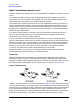
Figure 7-24 Sources of Error in a Reflection Measurement
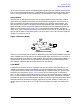
To characterize the errors, the reflection coefficient is measured by first separating the
incident signal (I) from the reflected signal (R), then taking the ratio of the two values. See
Figure 7-25. Ideally, (R) consists only of the signal reflected by the test device (S
11A
, for S
11
actual).
Figure 7-25 Reflection Coefficient