
User`s guide


1-46
Making Measurements
Measuring Electrical Length and Phase Distortion
Measuring Phase Distortion
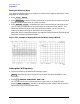
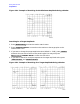
This portion of the example shows you how to measure the linearity of the phase shift over
a range of frequencies. The analyzer allows you to measure this linearity and read it in two
different ways: deviation from linear phase, or group delay.
Deviation From Linear Phase
By adding electrical length to “flatten out” the phase response, you have removed the
linear phase shift through your device. The deviation from linear phase shift through your
device is all that remains.
1. Follow the procedure in "Measuring Electrical Length" on page 1-43.
2. To increase the scale resolution, press:
and turn the front panel knob, or enter a value from the front
panel keypad.
3. To use the marker statistics to measure the maximum peak-to-peak deviation from
linear phase, press:
4. Activate and adjust the electrical delay to obtain a minimum peak-to-peak value.
NOTE It is possible to use delta markers to measure peak-to-peak deviation in only
one portion of the trace. See "To Calculate the Statistics of the Measurement
Data" on page 1-42.
Figure 1-36 Deviation From Linear Phase Example Measurement
Scale Ref
SCALE DIV
Marker Fctn
MKR MODE MENU
STATS ON