Agilent 3.
Notices © Agilent Technologies, Inc. 2006 No part of this manual may be reproduced in any form or by any means (including electronic storage and retrieval or translation into a foreign language) without prior agreement and written consent from Agilent Technologies, Inc. as governed by United States and international copyright laws. Manual Part Number N5980-91010 Edition Revision 1.0 May 2006 Printed in Germany Agilent Technologies, Deutschland GmbH Herrenberger Str.
Safety Summary General Safety Precautions General Ground the Instrument The following general safety precautions must be observed during all phases of operation of this instrument. Failure to comply with these precautions or with specific warnings elsewhere in this manual violates safety standards of design, manufacture, and intended use of the instrument. This product is a Safety Class 1 instrument (provided with a protective earth terminal).
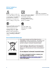
Safety Symbols on Instruments Indicates warning or caution. If you see this symbol on a product, you must refer to the manuals for specific Warning or Caution information to avoid personal injury or damage to the product. Safety requirements for electrical equipment for measurement, control, and laboratory use CAN/CSA C22.2 No. 1010.1 (1993) UL 3101, 3111 (First Editions). This equipment has also been evaluated to IEC 61010 edition 1 including amendments 1 and 2.
Contents Contents 1 Introduction 7 2 Getting Started 8 Inspect Shipment 8 Connect the Instrument 9 Front Panel 9 Rear Panel 10 Install User Software for N5980A 11 To Install the User Software for N5980A 12 To Access N5980A 14 3 Operating N5980A with the User Interface 16 Introduction 16 Running the BER Test 17 Setting the Instrument Parameters 18 Setup 18 Advanced 19 Viewing the Results 20 4 Reference for the User Interface 21 File Menu 21 Advanced Mode 21 Store Setting 21 Store Setting As 22 Reca
Contents Error 25 Sync Loss 25 Setup and Advanced Tab 26 Setup 26 Advanced 27 BER and Advanced BER Tab 28 BER 28 Advanced BER 29 5 Programming Reference 30 Introduction 30 Common Command Summary 30 Agilent N5980A Command Summary 30 SCPI Instrument Command List- Reference 31 Common Commands 31 All Channels 33 SMA Output (Electrical Generator) 34 SFP Output (Optical Generator) 36 Trigger Output 38 Synchronization mode 39 Sample Code 42 6 N5980A User Guide
Introduction 1 Introduction This chapter introduces you to the Serial BERT User Guide, and it provides information on the various chapters and topics covered.
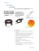
Getting Started 2 Getting Started Inspect Shipment Before you get started with the Serial BERT check if the shipment package contains the following standard deliverables: If the content is incomplete, if there is mechanical damage, or if the instrument does not work within its specifications, notify the nearest Agilent office. The Agilent office will arrange for repair or replacement without awaiting settlement. Agilent N5980A 3.
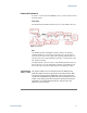
Getting Started Connect the Instrument In order to connect the Serial BERT let’s have a look at the Front and the Rear Panels: Front Panel The Front Panel has LEDs, Data In/Out ports, and an SFP connector. Figure 1 Front Panel SFP The Small Form Factor Pluggable interface (SFP) is an industry standard daughter card used in networking devices. It interfaces a network device with a networking cable.
Getting Started LED LEDs Function Power LED Indicates power-on USB Active Indicates that the instrument is currently being used/controlled by the user software Signal Detect Indicates the status of the Signal Detect line when the inserted SFP module supports a Signal Detect Control line. Usually this pin indicates whether the optical input power is above or within the specified range.
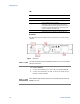
Getting Started Figure 3 Serial BERT setup diagram Install User Software for N5980A The requirements for software installation: NOTE N5980A User Guide Either Windows 2000 Service Pack 4, or Windows XP Service Pack 2 Microsoft .NET Framework 2.0 is automatically downloaded from the Microsoft download center during installation. Alternatively dotnetfx.exe may be run from the installation CD in order to install the Microsoft .Net Framework 2.0. This step should be executed in case .
Getting Started To Install the User Software for N5980A 1 Insert the CD in the PC’s CD Drive. 2 Double-click Displays the Welcome screen. 3 12 The Installer guides you through the installation process.
Getting Started Select the folder in which N5980A will be saved.
Getting Started After the installation is completed, click Finish to close the installer. To Access N5980A To launch N5980A, go to Program File and click on: If there is a N5980A connected to the PC via USB, and the User Software is installed, then the following screen appears: NOTE 14 Typical Hardware Initialization duration is between 3 to 5 minutes.
Getting Started Upon completion of Hardware Initialization, the User Interface starts and the following window appears. Demo Offline In Demo Offline mode N5980A need not be connected to the PC. The connection dialog looks like the screen below. Click Demo (Offline) to start the offline version of the GUI. NOTE Before disconnecting the USB cable, or powering down the instrument, make sure you have closed the User Software. .
Operating N5980A with the User Interface 3 Operating N5980A with the User Interface Introduction The graphical user interface runs on the PC, and the screen is divided into two areas; one for setting parameters, and the other for viewing results. The Setting Parameters area of the screen has options for setting parameters like Data Rate, Data Pattern and so on. The Viewing Results area of the screen runs the test, and displays the results.
Operating N5980A with the User Interface Running the BER Test The User Software supports a quick pass/fail measurement, which is generally used for testing the DUT in manufacturing. This measurement allows you to count the number of bit errors during a user specified gating time. The result of the measurement is displayed as Gating Errors, Gating BER, and by a simple red (=fail) / green (=pass) color coding of the Gating BER bar.
Operating N5980A with the User Interface Setting the Instrument Parameters N5980A has two (SFP and SMA) integrated Pattern Generators, which can be adjusted to different parameters, for example, different patterns or different error insertion rates. The N5980A Error Detector has two (SFP and SMA) different physical input ports, while only one input port can be analyzed at a given time. The analyzed input can be selected with the User Software. There are two setting pages, Setup and Advanced.
Operating N5980A with the User Interface Advanced To view the Advanced page, click on the File menu and enable the Advanced Mode: The Advanced page has the following settings: In this page you can set SFP and SMA Data Patterns, Error Insertion Rate, and also select Clock Trigger Output for the Generator. It also gives the option for setting the Gating Time for the Error Detector.
Operating N5980A with the User Interface Viewing the Results There are two options for viewing the results, BER and Advanced BER, as shown below. BER displays Gating BER and the Elapsed Gating Time. The Advanced BER page can be opened only when Advanced Mode is enabled. See below: In this page you can see the Gating Errors, Actual Errors , and the Pattern that is currently being used by the Error Detector.
Reference for the User Interface 4 Reference for the User Interface This section explains the measured parameters, and the display options that are specific to these measurements. Additionally, some information is provided to explain the theoretical background to these measurements. When N5980A is launched the following screen is displayed: File Menu The File menu has the following options.
Reference for the User Interface Store Setting As This is used to store/recall any setting with a user selected filename. The user selects a specific location, and file name to save the settings. Recall Setting This recalls the saved settings. Factory Default Setting Restores the factory default settings, and is useful when the user has problems finding a defined instrument state. Instrument Default Setting This is enabled only when Advanced Mode is on.
Reference for the User Interface Connect The Connect… option shows the Connection Dialog box. NOTE If there are no instruments connected to the PC, then Connect button will be disabled. If an instrument is connected, the user can connect to that instrument. In the Available Devices, the list of connected device will appear, and the Connect button will be enabled. NOTE Each PC can control only one N5980A. In Remote Programming Setup, a port number can be selected for the remote programming interface.
Reference for the User Interface Info This option provides the following information. Help Menu The Help Menu has the following information. About gives you the Software details. Error Indicators The GUI screen contains the Error Indicator: There are two indicators and a BER bar, see the screen above.
Reference for the User Interface BER Bar The BER bar displays the BER calculated during a period of 200 ms. Error This indicator turns red when errors are detected. Stable errors are caused by the error add function: it turns SFP/SMA Error Insertion Rate off. Variable and high errors may be caused by faulty connectors/cables. BERT connected to your device shows: Stable or variable errors caused by your device. Correct the problems with your device.
Reference for the User Interface Setup and Advanced Tab Setup General Data Rate: There are different data rates in the drop down list. These rates are common to the Generator, and the Error Detector. The following screen lists the available Data Rates. Generator Data Pattern: There are different patterns available, for example, PRBS patterns, Clock patterns, and K28.5 pattern. NOTE The drop down screen below lists the available patterns. To view all the patterns use the scroll bar.
Reference for the User Interface Error Detector Data Pattern: The Error Detector (ED) has a built in CDR for automatic clock recovery, and phase alignment. The ED also performs automatic polarity correction when required. Additionally it can detect the incoming PRBS. The input for the Data Pattern has two options, SMA [Electrical], and SFP [Optical]. SMA [Electrical] is the default input for the Error Detector. Automatic Error Detector determines the incoming data stream automatically.
Reference for the User Interface NOTE On the advanced page the SFP and the SMA Data pattern can be adjusted independently. SFP Error Insertion Rate: This drop down list gives a set of Error Insertion Rates that can be inserted for the SFP output. SMA Error Insertion Rate: This drop down list gives a set of Error Insertion Rates that can be inserted for the SFP output. NOTE Both the lists contain the same set of Error Insertion Rates. The following screen shows this list.
Reference for the User Interface The screenshot below shows the Gating BER Bar. Elapsed Gating Time This bar shows the gating time while the test runs. Before the test begins this bar is empty as shown below: And after the gating time is complete this bar appears as shown below: Advanced BER This page contains Gating Error, Actual Error, Error Detector Pattern Gating BER Bar, and Elapsed Gating Time. Gating Errors This indicates the number of Errors that occurred during the gating time.
Programming Reference 5 Programming Reference Introduction The SCPI commands represent the instrument’s advanced analysis, and pattern generation features that can be controlled from within the remote programs. Programming can only be done using raw Windows Sockets. The remote programming language is close to SCPI, but it’s without a full featured SCPI parser. Thus N5980A is not SCPI1997 compliant.
Programming Reference :SOUR1:VOLT :SOUR1:VOLT? :SOUR2:PATT :SOUR2:PATT? :SOUR2:PATT:EADD :SOUR2:PATT:EADD:RATE :SOUR2:PATT:EADD:RATE? :SOUR3:PATT? :SOUR3:PATT :SENS1:SYNC:TYPE :SENS1:SYNC:TYPE? :SENS1:PATT? :SENS1:GATE:PER :SENS1:GATE:PER? :SENS1:FETC:ECO? :SENS1:FETC:ECO:DELT? :SENS1:FETC:ERAT? :SENS1:FETC:ERAT:DELT? :SENS1:INP :SENS1:INP? :SENS1:GATE:STAT :SENS1:GATE:STAT? SCPI Instrument Command List- Reference The following reference section lists the instrument commands.
Programming Reference Read error queue :SYST:ERR? Syntax Description :SYST:ERR? Reads one error from the instruments error queue. Load factory default setting *RST Syntax Description *RST Discards the current instrument setting, and loads the reset/default setting. Operation complete *OPC? Syntax Description *OPC? Returns 1 when all pending commands have been executed. Blocks until all pending commands are executed. Option Query *OPT? Syntax Description *OPT? Reports all instrument options.
Programming Reference Store current setting :MMEM:STOR:STAT “filename” Syntax Description :MMEM:STOR:STAT “filename” Stores the current setting into the specified file. If a file with the same name already exists, then this file will be overwritten. Recall setting :MMEM:LOAD:STAT “filename” Syntax Description :MMEM:LOAD:STAT “filename” Loads stored instrument setting from the given file.
Programming Reference SMA Output (Electrical Generator) The SMA output is accessed via the root node :SOUR1 Pattern :SOUR1:PATT Syntax Description Available Patterns 34 :SOUR1:PATT? :SOUR1:PATT PRBS7|PRBS15|PRBS23|PRBS31|CLK2|CLK4|CLK8|CLK10|CLK16 |CLK20|K28_5 Either sets or gets the pattern of the SMA output.
Programming Reference Error Insertion The error insertion is capable to enforce a given error ratio, and to add single errors into the data stream. Both are available in parallel. Insertion Rate :SOUR1:PATT:EADD:RATE Syntax Description :SOUR1:PATT:EADD:RATE? :SOUR1:PATT:EADD:RATE NR3 Either sets or gets the error insertion rate. Only the listed error rates are available. If another value is specified while sending the command, the error rate will be rounded to the next available value.
Programming Reference SFP Output (Optical Generator) The SFP output is accessed via the root node :SOUR2 Pattern :SOUR2:PATT Syntax Description Available Patterns 36 :SOUR2:PATT? :SOUR2:PATT PRBS7|PRBS15|PRBS23|PRBS31|CLK2|CLK4|CLK8|CLK10|CLK16 |CLK20|K28_5 Either sets or gets the pattern of the SFP output.
Programming Reference Error Insertion The error insertion is capable to enforce a given error ratio, and to add single errors into the data stream. Both are available in parallel. Insertion Rate :SOUR2:PATT:EADD:RATE Syntax Description :SOUR2:PATT:EADD:RATE? :SOUR2:PATT:EADD:RATE NR3 Either sets or gets the error insertion rate. Only the listed error rates are available. If another value is specified while sending the command, the error rate will be rounded to the next available value.
Programming Reference Trigger Output The trigger output is accessible via the root node :SOUR3 Pattern :SOUR3:PATT Syntax Description :SOUR3:PATT? :SOUR3:PATT CLK2|CLK4|CLK8|CLK10|CLK16|CLK20 Either sets or gets the pattern of the trigger output.
Programming Reference Synchronization mode :SENS1:SYNC:TYPE Syntax :SENS1:SYNC:TYPE AUTO|SFP|SMA|PRBS7|PRBS15|PEBS23|PRBS31 :SENS1:SYNC:TYPE? Description Either sets or gets the synchronization type. The synchronization type defines which patterns will be used to synchronize when a synchronization loss is detected by the Error Detector.
Programming Reference Gating Time :SENS1:GATE:PER Syntax Description :SENS1:GATE:PER? :SENS1:GATE:PER integer Either gets or sets the duration of the gating interval. The allowed range for the gating time is 1s to 608399s (168 hours, 59 minutes, 59 seconds). The gating time is always in seconds. Fractional seconds are not supported, and will be rounded to the closest time in seconds.
Programming Reference Gating Progress :SENS1:GATE:STAT Syntax Description :SENS1:GATE:STAT? Requests the current state of the gating interval. It will return 1 while the gating is in progress and 0 if the gating is finished/ inactive. It is guaranteed that the very first :SENS1:GATE:STAT? query after the start of the gating period will report a valid state of the gating progress. There is no need to capture 0-1-0 transitions of the gating progress.
Programming Reference Sample Code The following example code shows how to control the N5980A from within a remote program. The example code is implemented in C#. The code snippets show the required code that needs to be added to a user program. It implements a class N5980A in the namespace N5980AExample that allows communication with the N5980A user software. using using using using using using System; System.Collections.Generic; System.Text; System.Net; System.Net.Sockets; System.Windows.
Programming Reference /// public void Disconnect() { if (m_Client != null) m_Client.Close(); } /// /// Write to a SCPI command to a network socket and return the /// response if it was a query. /// /// SCPI command to be written to the socket /// Response of the instrument or an empty string /// if there is no response.
Programming Reference { /// /// The main entry point for the application. /// [STAThread] static void Main() { N5980A instrument = new N5980A(); // Connect to the N5980A software running on the same // PC as this program and that is using port number 5025 instrument.Connect("localhost", 5025); // set the data rate to OC-3 instrument.Send(":freq OC3"); // read the data rate string response = instrument.Send(":freq?"); // Close the socket => disconnect from the instrument instrument.