Agilent 34401A 6 ½ Digit Multimeter User’s Guide Agilent Technologies
Notices © Agilent Technologies, Inc. 1991 - 2007 Warranty No part of this manual may be reproduced in any form or by any means (including electronic storage and retrieval or translation into a foreign language) without prior agreement and written consent from Agilent Technologies, Inc. as governed by United States and international copyright laws. The material contained in this document is provided “as is,” and is subject to being changed, without notice, in future editions.
Safety Information General Do not use this product in any manner not specified by the manufacturer. The protective features of this product may be impaired if it is used in a manner not specified in the operation instructions. Do not install substitute parts or perform any unauthorized modification to the product. Return the product to an Agilent Technologies Sales and Service Office for service and repair to ensure that safety features are maintained.
LO to Ground Protection Limit. The LO input terminal can safely "float" a maximum of 500 Vpk relative to ground. WARN IN G IEC Measurement Category II. The HI and LO input terminals may be connected to mains in IEC Category II installations for line voltages up to 300 VAC. To avoid the danger of electric shock, do not connect the inputs to mains for line voltages above 300 VAC. See "IEC Measurement Category II Overvoltage Protection" on the following page for further information.
IEC Measurement Category II includes electrical devices connected to mains at an outlet on a branch circuit. Such devices include most small appliances, test equipment, and other devices that plug into a branch outlet or socket. The 34401A may be used to make measurements with the HI and LO inputs connected to mains in such devices, or to the branch outlet itself (up to 300 VAC).
DECLARATION OF CONFORMITY According to ISO/IEC Guide 22 and CEN/CENELEC EN 45014 Manufacturer’s Name: Manufacturer’s Address: Agilent Technologies, Incorporated th 815 – 14 St. SW Loveland, Colorado 80537 USA Declares, that the product Product Name: Model Number: Product Options: Multimeter 34401A This declaration covers all options of the above product(s).
Note: Unless otherwise indicated, this manual applies to all Serial Numbers. The Agilent Technologies 34401A is a 61⁄2-digit, high-performance digital multimeter. Its combination of bench-top and system features makes this multimeter a versatile solution for your measurement needs now and in the future.
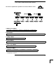
The Front Panel at a Glance 1 2 3 4 2 Measurement Function keys Math Operation keys Single Trigger / Autotrigger / Reading Hold key Shift / Local key 5 Front / Rear Input Terminal Switch 6 Range / Number of Digits Displayed keys 7 Menu Operation keys
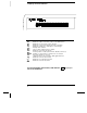
The Front-Panel Menu at a Glance The menu is organized in a top-down tree structure with three levels.
Display Annunciators ∗ Adrs Rmt Man Trig Hold Mem Ratio Math ERROR Rear Shift 4W Turns on during a measurement. Multimeter is addressed to listen or talk over the GPIB interface. Multimeter is in remote mode (remote interface). Multimeter is using manual ranging (autorange is disabled). Multimeter is waiting for a single trigger or external trigger. Reading Hold is enabled. Turns on when reading memory is enabled. Multimeter is in dcv:dcv ratio function.
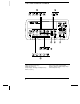
The Rear Panel at a Glance 1 2 3 4 Chassis Ground Power-Line Fuse-Holder Assembly Power-Line Voltage Setting Front and Rear Current Input Fuse 5 6 7 8 Voltmeter Complete Output Terminal External Trigger Input Terminal GPIB (IEEE-488) Interface connector RS-232 interface connector Use the front-panel Input / Output Menu to: • • • Select the GPIB or RS-232 interface (see chapter 4). Set the GPIB bus address (see chapter 4). Set the RS-232 baud rate and parity (see chapter 4).
In This Book Quick Start Chapter 1 prepares the multimeter for use and helps you get familiar with a few of its front-panel features. Front-Panel Menu Operation Chapter 2 introduces you to the front-panel menu and describes some of the multimeter’s menu features. Features and Functions Chapter 3 gives a detailed description of the multimeter’s capabilities and operation. You will find this chapter useful whether you are operating the multimeter from the front panel or over the remote interface.
Contents Chapter 1 Quick Start To Prepare the Multimeter for Use 13 If the Multimeter Does Not Turn On 14 To Adjust the Carrying Handle 16 To Measure Voltage 17 To Measure Resistance 17 To Measure Current 18 To Measure Frequency (or Period) 18 To Test Continuity 19 To Check Diodes 19 To Select a Range 20 To Set the Resolution 21 Front-Panel Display Formats 22 To Rack Mount the Multimeter 23 Chapter 2 Front-Panel Menu Operation Contents Front-Panel Menu Reference 27 A Front-Panel Menu Tutorial 29 To Turn
Contents Contents Chapter 3 Features and Functions (continued) Math Operations Min-Max Operation 64 Null (Relative) Operation 65 dB Measurements 67 dBm Measurements 68 Limit Testing 69 Triggering Trigger Source Choices 73 The Wait-for-Trigger State 76 Halting a Measurement in Progress 76 Number of Samples 77 Number of Triggers 78 Trigger Delay 79 Automatic Trigger Delays 81 Reading Hold 82 Voltmeter Complete Terminal 83 External Trigger Terminal 83 System-Related Operations Reading Memory 84 Error Conditi
Contents Chapter 4 Remote Interface Reference Contents Command Summary 105 Simplified Programming Overview 112 The MEASure? and CONFigure Commands 117 Measurement Configuration Commands 121 Math Operation Commands 124 Triggering 127 Triggering Commands 130 System-Related Commands 132 The SCPI Status Model 134 Status Reporting Commands 144 Calibration Commands 146 RS-232 Interface Configuration 148 RS-232 Interface Commands 153 An Introduction to the SCPI Language 154 Output Data Formats 159 Using Device
Contents Contents Chapter 7 Measurement Tutorial Thermal EMF Errors 199 Loading Errors (dc volts) 199 Leakage Current Errors 199 Rejecting Power-Line Noise Voltages 200 Common Mode Rejection (CMR) 201 Noise Caused by Magnetic Loops 201 Noise Caused by Ground Loops 202 Resistance Measurements 203 4-Wire Ohms Measurements 203 Removing Test Lead Resistance Errors 204 Power Dissipation Effects 204 Settling Time Effects 204 Errors in High Resistance Measurements 205 DC Current Measurement Errors 205 True RMS A
1 1 Quick Start
Quick Start One of the first things you will want to do with your multimeter is to become acquainted with its front panel. We have written the exercises in this chapter to prepare the multimeter for use and help you get familiar with some of its front-panel operations. The front panel has two rows of keys to select various functions and operations. Most keys have a shifted function printed in blue above the key. To perform a shifted function, press Shift (the Shift annunciator will turn on).
Chapter 1 Quick Start To Prepare the Multimeter for Use 1 To Prepare the Multimeter for Use The following steps help you verify that the multimeter is ready for use. 1 Check the list of supplied items. Verify that you have received the following items with your multimeter. If anything is missing, contact your nearest Agilent Sales Office. One test lead kit. One power cord. This User’s Guide. One Service Guide. One folded Quick Reference card. Certificate of Calibration.
Chapter 1 Quick Start If the Multimeter Does Not Turn On 1 If the Multimeter Does Not Turn On Use the following steps to help solve problems you might encounter when turning on the multimeter. If you need more help, see the Service Guide for instructions on returning the multimeter to Agilent for service. 1 Verify that there is ac power to the multimeter. First, verify that the multimeter’s Power switch is in the “On” position.
Chapter 1 Quick Start If the Multimeter Does Not Turn On 1 1 Remove the power cord. Remove the fuse-holder assembly from the rear panel. 2 Remove the line-voltage selector from the assembly. See rear panel for proper fuse rating. Agilent Part Number: 2110-0817 (250 mAT) 3 Rotate the line-voltage selector until the correct voltage appears in the window. 4 Replace the fuse-holder assembly in the rear panel.
Chapter 1 Quick Start To Adjust the Carrying Handle To Adjust the Carrying Handle To adjust the position, grasp the handle by the sides and pull outward. Then, rotate the handle to the desired position.
Chapter 1 Quick Start To Measure Voltage 1 To Measure Voltage Ranges: 100 mV, 1 V, 10 V, 100 V, 1000 V (750 Vac) Maximum resolution: 100 nV (on 100 mV range) AC technique: true RMS, ac-coupled To Measure Resistance Ranges: 100 Ω, 1 kΩ, 10 kΩ, 100 kΩ, 1 MΩ, 10 MΩ, 100 MΩ Maximum resolution: 100 µΩ (on 100 ohm range) 17
Chapter 1 Quick Start To Measure Current To Measure Current Ranges: 10 mA (dc only), 100 mA (dc only), 1 A , 3 A Maximum resolution: 10 nA (on 10 mA range) AC technique: true RMS, ac-coupled To Measure Frequency (or Period) Measurement band: 3 Hz to 300 kHz (0.33 sec to 3.
Chapter 1 Quick Start To Test Continuity 1 To Test Continuity Test current source: 1 mA Maximum resolution: 0.1 Ω (range is fixed at 1 kohm) Beeper threshold: 1 Ω to 1000 Ω (beeps below adjustable threshold) To Check Diodes Test current source: 1 mA Maximum resolution: 100 µV (range is fixed at 1 Vdc) Beeper threshold: 0.3 volts ≤ Vmeasured ≤ 0.
Chapter 1 Quick Start To Select a Range To Select a Range You can let the multimeter automatically select the range using autoranging or you can select a fixed range using manual ranging. Selects a lower range and disables autoranging. Selects a higher range and disables autoranging. Man annunciator is on when manual range is enabled. Toggles between autoranging and manual ranging. • Autoranging is selected at power-on and after a remote interface reset.
Chapter 1 Quick Start To Set the Resolution 1 To Set the Resolution You can set the display resolution to 41⁄2, 51⁄2, or 61⁄2 digits either to optimize measurement speed or noise rejection. In this book, the most significant digit (leftmost on the display) is referred to as the “1⁄2” digit, since it can only be a “0” or “1.” Press the Shift key. Selects 41⁄2 digits. Selects 51⁄2 digits. Selects 61⁄2 digits (most noise rejection).
Chapter 1 Quick Start Front-Panel Display Formats Front-Panel Display Formats -H.DDD,DDD EFFF Front-panel display format. – H D E F Negative sign or blank (positive) “ 1⁄2 ” digit (0 or 1) Numeric digits Exponent ( m, k, M ) Measurement units ( VDC, OHM, HZ, dB ) 5 digits 10.216,5 “ 1⁄2” digit VDC This is the 10 Vdc range, 51⁄2 digits are displayed. “ 1⁄2” digit -045.23 mVDC This is the 100 mVdc range, 41⁄2 digits are displayed. 113.
Chapter 1 Quick Start To Rack Mount the Multimeter 1 To Rack Mount the Multimeter You can mount the multimeter in a standard 19-inch rack cabinet using one of three optional kits available. Instructions and mounting hardware are included with each rack-mounting kit. Any Agilent System II instrument of the same size can be rack-mounted beside the 34401A. Remove the carrying handle, and the front and rear rubber bumpers, before rack-mounting the multimeter.
Chapter 1 Quick Start To Rack Mount the Multimeter To rack mount a single instrument, order adapter kit 5063-9240. To rack mount two instruments side-by-side, order lock-link kit 5061-9694 and flange kit 5063-9212. To install one or two instruments in a sliding support shelf, order shelf 5063-9255, and slide kit 1494-0015 (for a single instrument, also order filler panel 5002-3999).
2 2 Front-Panel Menu Operation
Front-Panel Menu Operation By now you should be familiar with the FUNCTION and RANGE / DIGITS groups of front-panel keys. You should also understand how to make front-panel connections for the various types of measurements. If you are not familiar with this information, we recommend that you read chapter 1, “Quick Start,” starting on page 11. This chapter introduces you to three new groups of front-panel keys: MENU, MATH, and TRIG.
Chapter 2 Front-Panel Menu Operation Front-Panel Menu Reference Front-Panel Menu Reference 2 A: MEASurement MENU 1: AC FILTER > 2: CONTINUITY > 3: INPUT R > 4: RATIO FUNC > 5: RESOLUTION 1: 2: 3: 4: 5: AC FILTER CONTINUITY INPUT R RATIO FUNC RESOLUTION Selects the slow, medium, or fast ac filter. Sets the continuity beeper threshold (1 Ω to 1000 Ω). Sets the input resistance for dc voltage measurements. Enables the dcv:dcv ratio function. Selects the measurement resolution.
Chapter 2 Front-Panel Menu Operation Front-Panel Menu Reference D: SYStem MENU 1: RDGS STORE > 2: SAVED RDGS > 3: ERROR > 4: TEST > 5: DISPLAY > 6: BEEP > 7: COMMA > 8: REVISION 1: 2: 3: 4: 5: 6: 7: 8: RDGS STORE SAVED RDGS ERROR TEST DISPLAY BEEP COMMA REVISION Enables or disables reading memory. Recalls readings stored in memory (up to 512 readings). Retrieves errors from the error queue (up to 20 errors). Performs a complete self-test. Enables or disables the front-panel display.
Chapter 2 Front-Panel Menu Operation A Front-Panel Menu Tutorial A Front-Panel Menu Tutorial This section is a step-by-step tutorial which shows how to use the front-panel menu. We recommend that you spend a few minutes with this tutorial to get comfortable with the structure and operation of the menu. The menu is organized in a top-down tree structure with three levels (menus, commands, and parameters). You move down ∨ or up ∧ the menu tree to get from one level to the next.
Chapter 2 Front-Panel Menu Operation A Front-Panel Menu Tutorial MESSAGES DISPLAYED DURING MENU USE ∧ while on the “menus” level; this is the top level of the menu and you cannot go any higher. TOP OF MENU You pressed Shift < (Menu On/Off). To move across the choices To turn off the menu, press on a level, press < or > . To move down a level, press ∨ . MENUS You are on the “menus” level. Press < or > to view the choices. COMMANDS You are on the “commands” level.
Chapter 2 Front-Panel Menu Operation A Front-Panel Menu Tutorial Menu Example 1 The following steps show you how to turn on the menu, move up or down between levels, move across the choices on each level, and turn off the menu. In this example, you will turn off the front-panel beeper. 2 On/Off Shift < 1 Turn on the menu. You enter the menu on the “menus” level. The MEAS MENU is your first choice on this level. A: MEAS MENU > > > 2 Move across to the SYS MENU choice on this level.
Chapter 2 Front-Panel Menu Operation A Front-Panel Menu Tutorial > > > > > 4 Move across to the BEEP command on the “commands” level. There are eight command choices available in the SYS MENU. Each choice on this level has a number prefix for easy identification (1: , 2: , etc.). 6: BEEP ∨ 5 Move down a level to the BEEP parameter choices. The first parameter choice is “ON” for the BEEP command (the beeper setting is stored in non-volatile memory and “ON” is the factory setting).
Chapter 2 Front-Panel Menu Operation A Front-Panel Menu Tutorial Menu Example 2 The following exercise demonstrates how to use the menu recall feature as a shortcut to set the BEEP command back to its original setting. You must perform the steps in Example 1 before you start this example. 2 Recall Shift > 1 Use menu recall to return to the BEEP command. This returns you to the BEEP command, which was the last command used before you exited the menu in the Example 1.
Chapter 2 Front-Panel Menu Operation A Front-Panel Menu Tutorial Menu Example 3 Some commands in the menu require that you enter a numeric parameter value. The following steps show you how to enter a number in the menu. For this example, you will set the null value to –2.0 volts. Make sure the multimeter is in the dc voltage function with 51⁄2 digits of resolution displayed. Disconnect all inputs to the multimeter. On/Off Shift < 1 Turn on the menu. You enter the menu on the “menus” level.
Chapter 2 Front-Panel Menu Operation A Front-Panel Menu Tutorial ∨ 5 Move down to edit the NULL VALUE parameter. The null value should be 0.0 Vdc when you come to this point in the menu for the first time. For this example, you will set the null value to –2.0 volts. ∧000.000 2 mVDC When you see the flashing “∧” on the left side of the display, you can abort the edit and return to the “commands” level by pressing ∧ . ∨ ∨ 6 Make the number negative.
Chapter 2 Front-Panel Menu Operation A Front-Panel Menu Tutorial < < 9 Move the flashing cursor over to the “units” location. Notice that the units are flashing on the right side of the display. -200.000 ∧ mVDC 10 Increase the displayed number by a factor of 10. Notice that the position of the decimal point changes and the displayed number increases by a factor of 10. -2.000,00 Auto/Man VDC 11 Save the change and turn off the menu.
Chapter 2 Front-Panel Menu Operation To Turn Off the Comma Separator To Turn Off the Comma Separator The multimeter can display readings on the front panel with or without a comma separator. The following steps show how to disable the comma. 08.241,53 VDC With comma separator (factory setting) 08.24153 VDC Without comma separator On/Off Shift < 1 Turn on the menu. A: MEAS MENU > > > 2 Move across to the SYS MENU choice on the “menus” level.
Chapter 2 Front-Panel Menu Operation To Make Null (Relative) Measurements To Make Null (Relative) Measurements Each null measurement, also called relative, is the difference between a stored null value and the input signal. Result = reading – null value To read / edit the null value, use the MATH menu. Enables null operation; Press again to disable. Math annunciator is on when null operation is enabled. • You can make null measurements with any function except continuity, diode, or ratio.
Chapter 2 Front-Panel Menu Operation To Store Minimum and Maximum Readings To Store Minimum and Maximum Readings You can store the minimum and maximum readings during a series of measurements. The following discussion shows how to read the minimum, maximum, average, and reading count. 2 To read the minimum, maximum, average, and count, use the MATH menu. Enables min-max operation; Press again to disable. Math annunciator is on when min-max operation is enabled.
Chapter 2 Front-Panel Menu Operation To Make dB Measurements To Make dB Measurements Each dB measurement is the difference between the input signal and a stored relative value, with both values converted to dBm. dB = reading in dBm – relative value in dBm To read / edit the dB relative value, use the MATH menu. Enables dB operation; Press again to disable. Math annunciator is on when dB operation is enabled. • Select DC V or AC V .
Chapter 2 Front-Panel Menu Operation To Make dBm Measurements To Make dBm Measurements The dBm operation calculates the power delivered to a resistance referenced to 1 milliwatt. 2 dBm = 10 × Log10 ( reading2 / reference resistance / 1 mW ) To read / edit the dBm reference resistance, use the MATH menu. Enables dBm operation; Press again to disable. Math annunciator is on when dBm operation is enabled. • Select DC V or AC V . • The factory setting for the reference resistance is 600 Ω.
Chapter 2 Front-Panel Menu Operation To Trigger the Multimeter To Trigger the Multimeter You can trigger the multimeter from the front panel using single trigger or auto trigger. Enables single trigger and triggers the multimeter. ∗ (sample) annunciator is on during each measurement. Toggles between auto trigger and reading hold. Trig annunciator is on when the multimeter is waiting for single trigger (auto trigger disabled). • Auto triggering is enabled when you turn on the multimeter.
Chapter 2 Front-Panel Menu Operation To Use Reading Hold To Use Reading Hold The reading hold feature allows you to capture and hold a stable reading on the display. When a stable reading is detected, the multimeter emits a beep and holds the value on the display. 2 To adjust the reading hold sensitivity band, use the TRIG menu. Toggles between auto trigger and reading hold. Hold annunciator is on when reading hold is enabled.
Chapter 2 Front-Panel Menu Operation To Make dcv:dcv Ratio Measurements To Make dcv:dcv Ratio Measurements To calculate a ratio, the multimeter measures a dc reference voltage applied to the Sense terminals and the voltage applied to the Input terminals. Ratio = dc signal voltage dc reference voltage To enable ratio measurements, use the MEAS menu. Ratio annunciator is on when ratio measurements are enabled.
Chapter 2 Front-Panel Menu Operation To Make dcv:dcv Ratio Measurements The following steps show you how to select the ratio function using the front-panel menu. On/Off Shift < 1 Turn on the menu. 2 A: MEAS MENU ∨ < < 2 Move down a level and then across to the RATIO FUNC command. 4: RATIO FUNC ∨ 3 Move down to the “parameter” level. For this command, there is only one choice on this level. DCV:DCV Auto/Man 4 Select the ratio function and turn off the menu.
Chapter 2 Front-Panel Menu Operation To Use Reading Memory To Use Reading Memory The multimeter can store up to 512 readings in internal memory. The following steps demonstrate how to store readings and retrieve them. 1 Select the function. Select any measurement function. You can also select Null, Min–Max, dB, dBm, or limit test. You can change the function at any time during reading memory. Single 2 Select the single trigger mode. Notice that the Trig annunciator turns on.
Chapter 2 Front-Panel Menu Operation To Use Reading Memory ∨ > 6 Move down a level and then across to the “ON” choice. ON 2 Auto/Man 7 Save the change and exit the menu. ENTER Notice that the Mem (memory) annunciator turns on to indicate that the multimeter is ready to store readings. Up to 512 readings can be stored in first-in-first-out (FIFO) order. When memory is full, the Mem annunciator will turn off.
Chapter 2 Front-Panel Menu Operation To Use Reading Memory ∨ 10 Move down a level to view the first stored reading. Reading memory is automatically turned off when you go to the “parameter” level in the menu. The first reading displayed is the first reading that was stored (FIFO). If no readings are stored in memory, “EMPTY” is displayed. The stored readings are displayed with their units ( µ, m, k, etc.) when appropriate. For example: Reading number 10.
3 3 Features and Functions
Features and Functions You will find that this chapter makes it easy to look up all the details about a particular feature of the multimeter. Whether you are operating the multimeter from the front panel or from the remote interface, this chapter will be useful.
Chapter 3 Features and Functions Measurement Configuration Measurement Configuration This section contains information to help you configure the multimeter for making measurements. You may never have to change any of the measurement parameters discussed here, but they are provided to give you the flexibility you might need. AC Signal Filter The multimeter uses three different ac filters which enable you to either optimize low frequency accuracy or achieve faster ac settling times.
Chapter 3 Features and Functions Measurement Configuration Continuity Threshold Resistance When measuring continuity, the multimeter emits a continuous tone if the measured resistance is less than the threshold resistance. You can set the threshold to any value between 1 Ω and 1000 Ω . The threshold resistance is adjustable only from the front panel. • The threshold resistance is stored in non-volatile memory, and does not change when power has been off or after a remote interface reset.
Chapter 3 Features and Functions Measurement Configuration DC Input Resistance Normally, the multimeter’s input resistance is fixed at 10 MΩ for all dc voltage ranges to minimize noise pickup. To reduce the effects of measurement loading errors, you can set the input resistance to greater than 10 GΩ for the 100 mVdc, 1 Vdc, and 10 Vdc ranges. Applies to dc voltage measurements and is disabled for all other functions.
Chapter 3 Features and Functions Measurement Configuration Resolution Resolution is expressed in terms of number of digits the multimeter can measure or display. You can set the resolution to 4, 5, or 6 full digits, plus a “1⁄2” digit which can only be a “0” or “1”. To increase measurement accuracy and improve noise rejection, select 61⁄2 digits. To increase measurement speed, select 41⁄2 digits. Applies to all measurement functions.
Chapter 3 Features and Functions Measurement Configuration 5 digits 10.216,5 “ 1⁄2” digit VDC This is the 10 Vdc range, 51⁄2 digits are displayed. “ 1⁄2” digit -045.23 3 mVDC This is the 100 mVdc range, 41⁄2 digits are displayed. 113.325,6 OHM This is the 100 ohm range, 61⁄2 digits are displayed. • The resolution is stored in volatile memory; the multimeter sets the resolution to 51⁄2 digits (for all functions) when power has been off or after a remote interface reset.
Chapter 3 Features and Functions Measurement Configuration Resolution (continued) • Front-Panel Operation: Select either the slow or fast mode for each resolution setting. The default mode is 5 digits slow. 5: RESOLUTION (MEAS MENU) See also “To Set the Resolution,” on page 21. • Remote Interface Operation: You can set the resolution using the following commands.
Chapter 3 Features and Functions Measurement Configuration Integration Time Integration time is the period during which the multimeter’s analog-todigital (A/D) converter samples the input signal for a measurement. Integration time affects the measurement resolution (for better resolution, use a longer integration time), and measurement speed (for faster measurements, use a shorter integration time). Applies to all measurement functions except ac voltage, ac current, frequency, and period.
Chapter 3 Features and Functions Measurement Configuration Integration Time (continued) • Front-Panel Operation: Integration time is set indirectly when you select the number of digits. See the table for resolution on page 54. • Remote Interface Operation: :NPLCycles {0.02|0.2|1|10|100|MINimum|MAXimum} For frequency and period measurements, aperture time (or gate time) is analogous to integration time. Specify 10 ms (41⁄2 digits), 100 ms (default; 51⁄2 digits), or 1 second (61⁄2 digits).
Chapter 3 Features and Functions Measurement Configuration Autozero When autozero is enabled (default), the multimeter internally disconnects the input signal following each measurement, and takes a zero reading. It then subtracts the zero reading from the preceding reading. This prevents offset voltages present on the multimeter’s input circuitry from affecting measurement accuracy. When autozero is disabled, the multimeter takes one zero reading and subtracts it from all subsequent measurements.
Chapter 3 Features and Functions Measurement Configuration Autozero (continued) The following table shows the relationship between integration time and autozero settings from the remote interface and the corresponding front-panel settings.
Chapter 3 Features and Functions Measurement Configuration Ranging You can let the multimeter automatically select the range using autoranging or you can select a fixed range using manual ranging. Autoranging is convenient because the multimeter automatically selects the appropriate range for each measurement. However, you can use manual ranging for faster measurements since the multimeter does not have to determine which range to use for each measurement.
Chapter 3 Features and Functions Measurement Configuration Ranging (continued) • Front-Panel Operation: Use the front-panel RANGE keys to select autoranging or manual ranging. For frequency and period measurements from the front panel, ranging applies to the signal’s input voltage, not its frequency. See also “To Select a Range,” on page 20. • Remote Interface Operation: You can set the range using any of the following commands.
Chapter 3 Features and Functions Math Operations Math Operations There are five math operations available, only one of which can be enabled at a time. Each math operation performs a mathematical operation on each reading or stores data on a series of readings. The selected math operation remains in effect until you disable it, change functions, turn off the power, or perform a remote interface reset. The math operations use one or more internal registers.
Chapter 3 Features and Functions Math Operations Min–Max Operation The min-max operation stores the minimum and maximum readings during a series of measurements. The multimeter then calculates the average of all readings and records the number of readings taken since min-max was enabled. Applies to all measurement functions, except continuity and diode. • After you enable min-max, the first reading that the multimeter takes is stored as both the minimum and maximum value.
Chapter 3 Features and Functions Math Operations • Remote Interface Operation: You can use the following commands to make min-max measurements.
Chapter 3 Features and Functions Math Operations Null (Relative) (continued) • The null value is stored in the multimeter’s Null Register. There are two ways you can specify the null value. First, you can enter a specific number into the register from the front-panel menu or from the remote interface. Any previously stored value is replaced with the new value. If you are operating the multimeter from the front panel, entering a null value also turns on the null function.
Chapter 3 Features and Functions Math Operations dB Measurements Each dB measurement is the difference between the input signal and a stored relative value, with both values converted to dBm. dB = reading in dBm – relative value in dBm Applies to dc voltage and ac voltage measurements only. • The relative value is adjustable and you can set it to any value between 0 dBm and ±200.00 dBm.
Chapter 3 Features and Functions Math Operations • Remote Interface Operation: You can use the following commands to make dB measurements. Math must be enabled before you can store a value to the Relative Register. CALCulate:FUNCtion DB CALCulate:STATe {OFF|ON} CALCulate:DB:REFerence {|MINimum|MAXimum} dBm Measurements The dBm operation calculates the power delivered to a resistance referenced to 1 milliwatt.
Chapter 3 Features and Functions Math Operations Limit Testing The limit test operation enables you to perform pass/fail testing to upper and lower limits that you specify. Applies to all measurement functions, except continuity and diode tests. • You can set the upper and lower limits to any value between 0 and ±120% of the highest range, for the present function. The upper limit selected should always be a more positive number than the lower limit. The default upper and lower limits are both “0”.
Chapter 3 Features and Functions Math Operations Limit Testing (continued) • Remote Interface Operation: You can use the following commands for limit testing. CALCulate:FUNCtion LIMit CALCulate:STATe {OFF|ON} CALCulate:LIMit:LOWer {|MINimum|MAXimum} CALCulate:LIMit:UPPer {|MINimum|MAXimum} • There are two unused pins on the RS-232 interface connector which are available to indicate the pass/fail status of readings taken with limit testing.
Chapter 3 Features and Functions Triggering Triggering The multimeter’s triggering system allows you to generate triggers either manually or automatically, take multiple readings per trigger, and insert a delay before each reading. Normally, the multimeter will take one reading each time it receives a trigger, but you can specify multiple readings (up to 50,000) per trigger. You can trigger the multimeter from the front panel using a single trigger, an external trigger, or auto triggering.
Chapter 3 Features and Functions Triggering Agilent 34401A Triggering System Initiate Triggering MEASure? READ? INITiate Trigger Source TRIGger:SOURce IMMediate TRIGger:SOURce EXTernal TRIGger:SOURce BUS Front-panel “Single” key Idle State Wait-forTrigger State Trigger Delay TRIGger:DELay Sample ( ∗ ) Annunciator 72 Delay Measurement Sample Sample Count ≠ 1 Trigger Count ≠ 1
Chapter 3 Features and Functions Triggering Trigger Source Choices You must specify the source from which the multimeter will accept a trigger. From the front panel, the multimeter will accept a single trigger, a hardware trigger from the Ext Trig terminal, or continuously take readings using auto trigger. At power-on, auto triggering is used. From the remote interface, the multimeter will accept a software (bus) trigger, a hardware trigger from the Ext Trig terminal, or an immediate internal trigger.
Chapter 3 Features and Functions Triggering External Triggering In the external trigger mode, the multimeter will accept a hardware trigger applied to the Ext Trig terminal. The multimeter takes one reading, or the specified number of readings (sample count), each time Ext Trig receives a low-true pulse. See also “External Trigger Terminal,” on page 83. • The multimeter buffers one external trigger.
Chapter 3 Features and Functions Triggering Internal Triggering In the internal trigger mode (remote interface only), the trigger signal is always present. When you place the multimeter in the wait-for-trigger state, the trigger is issued immediately. This is the power-on trigger source for remote interface operation. To select the internal trigger source, send the following command. The CONFigure and MEASure? commands automatically set the trigger source to IMMediate.
Chapter 3 Features and Functions Triggering The Wait-for-Trigger State After you have configured the multimeter and selected a trigger source, you must place the multimeter in the wait-for-trigger state. A trigger will not be accepted until the multimeter is in this state. If a trigger signal is present, and if multimeter is in the “wait-for-trigger” state, the measurement sequence begins and readings are taken. The “wait-for-trigger” state is a term used primarily for remote interface operation.
Chapter 3 Features and Functions Triggering Number of Samples Normally, the multimeter takes one reading (or sample) each time it receives a trigger from the selected trigger source (if the multimeter is in the wait-for-trigger state). You can, however, instruct the multimeter to take multiple readings for each trigger received. • Number of samples: 1 to 50,000. The default is 1 sample per trigger.
Chapter 3 Features and Functions Triggering Number of Triggers Normally, the multimeter will accept only one trigger before returning to the “idle” trigger state. You can, however, instruct the multimeter to accept multiple triggers. This feature is available only from the remote interface. If you set the trigger count and then go to local (front panel), the multimeter ignores the trigger count setting; when you return to remote, the trigger count returns to the value you selected.
Chapter 3 Features and Functions Triggering Trigger Delay You can insert a delay between the trigger signal and each sample that follows. This may be useful in applications where you want to allow the input to settle before taking a reading, or for pacing a burst of readings. If you do not specify a trigger delay, the multimeter automatically selects a delay for you. • Delay range: 0 to 3600 seconds.
Chapter 3 Features and Functions Triggering Trigger Delay (continued) • Front-Panel Operation (continued) To set the delay to 0 seconds, select the “parameter” level of the TRIG DELAY command. Move the flashing cursor to the “units” location on the right side of the display. Press ∨ until ZERO DELAY is reached, then press Menu Enter. ZERO DELAY To select the automatic trigger delay, select the “parameter” level of the TRIG DELAY command.
Chapter 3 Features and Functions Triggering Automatic Trigger Delays If you do not specify a trigger delay, the multimeter selects an automatic delay for you. The delay is determined by function, range, integration time, and ac filter setting. • DC Voltage and DC Current (for all ranges): Integration Time Trigger Delay NPLC ≥ 1 NPLC < 1 • Trigger Delay (For NPLC ≥ 1) 100 Ω 1 kΩ 10 kΩ 100 kΩ 1 MΩ 10 MΩ 100 MΩ 1.5 ms 1.5 ms 1.5 ms 1.
Chapter 3 Features and Functions Triggering Reading Hold The reading hold feature allows you to capture and hold a stable reading on the front-panel display. This is especially useful in situations where you want to take a reading, remove the test probes, and have the reading remain on the display. When a stable reading is detected, the multimeter emits a beep (if the front-panel beeper is enabled) and holds the reading on the display. See also “Beeper Control,” on page 88.
Chapter 3 Features and Functions Triggering Voltmeter Complete Terminal The rear-panel VM Comp (voltmeter complete) terminal provides a low-true pulse after the completion of each measurement. Voltmeter complete and external trigger (see below) implement a standard hardware handshake sequence between measurement and switching devices.
Chapter 3 Features and Functions System-Related Operations System-Related Operations This section gives information on topics such as reading memory, errors, self-test, and front-panel display control. This information is not directly related to making measurements but is an important part of operating the multimeter. Reading Memory The multimeter can store up to 512 readings in internal memory. Readings are stored in first-in-first-out (FIFO) order. The first reading returned is the first reading stored.
Chapter 3 Features and Functions System-Related Operations Error Conditions When the front-panel ERROR annunciator turns on, one or more command syntax or hardware errors have been detected. A record of up to 20 errors is stored in the multimeter’s error queue. See chapter 5, “Error Messages,” for a complete listing of the errors. • Errors are retrieved in first-in-first-out (FIFO) order. The first error returned is the first error that was stored.
Chapter 3 Features and Functions System-Related Operations Self-Test A power-on self-test occurs automatically when you turn on the multimeter. This limited test assures you that the multimeter is operational. This self-test does not perform the extensive set of analog tests that are included as part of the complete self-test described below. A complete self-test runs a series of tests and takes approximately 15 seconds to execute.
Chapter 3 Features and Functions System-Related Operations Display Control To speed up your measurement rate, or for security reasons, you may want to turn off the front-panel display. From the remote interface, you can also display a 12-character message on the front panel. • When the display is turned off, readings are not sent to the display and all display annunciators except ERROR and Shift are disabled. Front-panel operation is otherwise unaffected by turning off the display.
Chapter 3 Features and Functions System-Related Operations Beeper Control Normally, the multimeter will emit a tone whenever certain conditions are met from the front panel. For example, the multimeter will beep when a stable reading is captured in reading hold. You may want to disable the front-panel beeper for certain applications. • When you disable the beeper, the multimeter will not emit a tone when: 1) a new minimum or maximum is found in a min–max test.
Chapter 3 Features and Functions System-Related Operations Comma Separators The multimeter can display readings on the front panel with or without a comma separator. This feature is available only from the front panel. 08.241,53 VDC 08.24153 With comma separator (factory setting) VDC Without comma separator • The display format is stored in non-volatile memory, and does not change when power has been off or after a remote interface reset.
Chapter 3 Features and Functions System-Related Operations SCPI Language Version Query The multimeter complies with the rules and regulations of the present version of SCPI (Standard Commands for Programmable Instruments). You can determine the SCPI version with which the multimeter is in compliance by sending a command from the remote interface. You cannot query the SCPI version from the front panel. • The following command returns the SCPI version. SYSTem:VERSion? Returns a string in the form “YYYY.
Chapter 3 Features and Functions Remote Interface Configuration Remote Interface Configuration This section gives information on configuring the remote interface. For additional information, see chapter 4, “Remote Interface Reference,” starting on page 103. GPIB Address Each device on the GPIB (IEEE-488) interface must have a unique address. You can set the multimeter’s address to any value between 0 and 31. The address is set to “22” when the multimeter is shipped from the factory.
Chapter 3 Features and Functions Remote Interface Configuration Remote Interface Selection The multimeter is shipped with both an GPIB (IEEE-488) interface and an RS-232 interface. Only one interface can be enabled at a time. The GPIB interface is selected when the multimeter is shipped from the factory. The remote interface can be set only from the front-panel. • The interface selection is stored in non-volatile memory, and does not change when power has been off or after a remote interface reset.
Chapter 3 Features and Functions Remote Interface Configuration Baud Rate Selection (RS-232) You can select one of six baud rates for RS-232 operation. The rate is set to 9600 baud when the multimeter is shipped from the factory. The baud rate can be set only from the front-panel. • Select one of the following: 300, 600, 1200, 2400, 4800, or 9600 baud (factory setting).
Chapter 3 Features and Functions Remote Interface Configuration Programming Language Selection You can select one of three languages to program the multimeter from the selected remote interface. The language is SCPI when the multimeter is shipped from the factory. • Select one of the following: SCPI, Agilent 3478A, or Fluke 8840A. • The language selection is stored in non-volatile memory, and does not change when power has been off or after a remote interface reset.
Chapter 3 Features and Functions Calibration Overview Calibration Overview This section gives a brief introduction to the calibration features of the multimeter. For a more detailed discussion of the calibration procedures, see chapter 4 in the Service Guide. Calibration Security This feature allows you to enter a security code to prevent accidental or unauthorized calibrations of the multimeter. When you first receive your multimeter, it is secured.
Chapter 3 Features and Functions Calibration Overview Calibration Security (continued) To Unsecure for Calibration You can unsecure the multimeter for calibration either from the front panel or remote interface. The multimeter is secured when shipped from the factory, and the security code is set to “HP034401”. • Front-Panel Operation: 1: SECURED (CAL MENU) If the multimeter is secured, you will see the above command when you go into the CAL MENU.
Chapter 3 Features and Functions Calibration Overview To Secure Against Calibration You can secure the multimeter against calibration either from the front panel or remote interface. The multimeter is secured when shipped from the factory, and the security code is set to “HP034401”. Make sure you have read the security code rules on page 95 before attempting to secure the multimeter.
Chapter 3 Features and Functions Calibration Overview Calibration Security (continued) To Change the Security Code To change the security code, you must first unsecure the multimeter, and then enter a new code. Make sure you have read the security code rules on page 95 before attempting to secure the multimeter. • Front-Panel Operation: To change the security code, first make sure that the multimeter is unsecured.
Chapter 3 Features and Functions Calibration Overview Calibration Message You can use the calibration message feature to record calibration information about your multimeter. For example, you can store such information as the last calibration date, the next calibration due date, the multimeter’s serial number, or even the name and phone number of the person to contact for a new calibration. You can record information in the calibration message only from the remote interface.
Chapter 3 Features and Functions Operator Maintenance Operator Maintenance This section describes how to replace the power-line and current fuses. If you need additional information about replacing parts or repairing the multimeter, see the Service Guide. To Replace the Power-Line Fuse The power-line fuse is located within the multimeter’s fuse-holder assembly on the rear panel (see also page 15). See the rear panel of the multimeter for the proper fuse rating.
Chapter 3 Features and Functions Power-On and Reset State Power-On and Reset State The parameters marked with a bullet ( • ) are stored in non-volatile memory. The factory settings are shown. Measurement For your convenience, this table is duplicated on the rear cover of this manual and on the Quick Reference Card.
102
4 4 Remote Interface Reference
Remote Interface Reference • > • • • • • • • Command Summary, starting on page 105 Simplified Programming Overview, starting on page 112 The MEASure? and CONFigure Commands, starting on page 117 Measurement Configuration Commands, starting on page 121 Math Operation Commands, starting on page 124 Triggering, starting on page 127 Triggering Commands, starting on page 130 System-Related Commands, starting on page 132 • • • • • > • • • • • • • • • • • • The SCPI Status Model, starting on page 134 Status Rep
Chapter 4 Remote Interface Reference Command Summary Command Summary This section summarizes the SCPI (Standard Commands for Programmable Instruments) commands available to program the multimeter. Refer to the later sections in this chapter for more complete details on each command. Throughout this manual, the following conventions are used for SCPI command syntax. Square brackets ( [ ] ) indicate optional keywords or parameters. Braces ( { } ) enclose parameters within a command string.
Chapter 4 Remote Interface Reference Command Summary Measurement Configuration Commands (see page 121 for more information) [SENSe:] FUNCtion "VOLTage:DC" FUNCtion "VOLTage:DC:RATio" FUNCtion "VOLTage:AC" FUNCtion "CURRent:DC" FUNCtion "CURRent:AC" FUNCtion "RESistance" (2-wire ohms) FUNCtion "FRESistance" (4-wire ohms) FUNCtion "FREQuency" FUNCtion "PERiod" FUNCtion "CONTinuity" FUNCtion "DIODe" FUNCtion? [SENSe:] VOLTage:DC:RANGe {|MINimum|MAXimum} VOLTage:DC:RANGe? [MINimum|MAXimum] VOLTage:AC:R
Chapter 4 Remote Interface Reference Command Summary Measurement Configuration Commands (continued) [SENSe:] VOLTage:DC:RESolution {|MINimum|MAXimum} VOLTage:DC:RESolution? [MINimum|MAXimum] VOLTage:AC:RESolution {|MINimum|MAXimum} VOLTage:AC:RESolution? [MINimum|MAXimum] CURRent:DC:RESolution {|MINimum|MAXimum} CURRent:DC:RESolution? [MINimum|MAXimum] CURRent:AC:RESolution {|MINimum|MAXimum} CURRent:AC:RESolution? [MINimum|MAXimum] RESistance:RESolution {<
Chapter 4 Remote Interface Reference Command Summary Math Operation Commands (see page 124 for more information) CALCulate :FUNCtion {NULL|DB|DBM|AVERage|LIMit} :FUNCtion? :STATe {OFF|ON} :STATe? CALCulate :AVERage:MINimum? :AVERage:MAXimum? :AVERage:AVERage? :AVERage:COUNt? CALCulate :NULL:OFFSet {|MINimum|MAXimum} :NULL:OFFSet? [MINimum|MAXimum] CALCulate :DB:REFerence {|MINimum|MAXimum} :DB:REFerence? [MINimum|MAXimum] CALCulate :DBM:REFerence {|MINimum|MAXimum} :DBM:REFerence? [M
Chapter 4 Remote Interface Reference Command Summary Triggering Commands (see page 127 for more information) INITiate READ? TRIGger :SOURce {BUS|IMMediate |EXTernal} :SOURce? TRIGger :DELay {|MINimum|MAXimum} :DELay? [MINimum|MAXimum] TRIGger :DELay:AUTO {OFF|ON} :DELay:AUTO? SAMPle :COUNt {|MINimum|MAXimum} :COUNt? [MINimum|MAXimum] 4 TRIGger :COUNt {|MINimum|MAXimum|INFinite} :COUNt? [MINimum|MAXimum] System-Related Commands (see page 132 for more information) SYSTem:ERRor? FE
Chapter 4 Remote Interface Reference Command Summary Status Reporting Commands (see page 144 for more information) SYSTem:ERRor? STATus :QUEStionable:ENABle :QUEStionable:ENABle? :QUEStionable:EVENt? STATus:PRESet *CLS *ESE *ESE? *ESR? *OPC *OPC? *PSC {0|1} *PSC? *SRE *SRE? *STB? Calibration Commands (see page 146 for more information) CALibration? CALibration:COUNt? CALibration :SECure:CODE :SECure:STATe {OFF|ON}, :SECure:STATe? CALibration
Chapter 4 Remote Interface Reference Command Summary RS-232 Interface Commands (see page 148 for more information) SYSTem:LOCal SYSTem:REMote SYSTem:RWLock IEEE-488.2 Common Commands (see page 169 for more information) *CLS *ESE *ESE? 4 *ESR? *IDN? *OPC *OPC? *PSC {0|1} *PSC? *RST *SRE *SRE? *STB? *TRG *TST? Default parameters are shown in bold.
Chapter 4 Remote Interface Reference Simplified Programming Overview Simplified Programming Overview First-time SCPI users, see page 154. You can program the multimeter to take measurements from the remote interface using the following simple seven-step sequence. 1. 2. 3. 4. 5. 6. 7. Place the multimeter in a known state (often the reset state). Change the multimeter’s settings to achieve the desired configuration. Set-up the triggering conditions. Initiate or arm the multimeter for a measurement.
Chapter 4 Remote Interface Reference Simplified Programming Overview Using the MEASure? Command The easiest way to program the multimeter for measurements is by using the MEASure? command. However, this command does not offer much flexibility. When you execute the command, the multimeter presets the best settings for the requested configuration and immediately performs the measurement. You cannot change any settings (other than function, range, and resolution) before the measurement is taken.
Chapter 4 Remote Interface Reference Simplified Programming Overview Using the range and resolution Parameters With the MEASure? and CONFigure commands, you can select the measurement function, range, and resolution all in one command. Use the range parameter to specify the expected value of the input signal. The multimeter then selects the correct measurement range. For frequency and period measurements, the multimeter uses one “range” for all inputs between 3 Hz and 300 kHz.
Chapter 4 Remote Interface Reference Simplified Programming Overview Caution If you send two query commands without reading the response from the first, and then attempt to read the second response, you may receive some data from the first response followed by the complete second response. To avoid this, do not send a query command without reading the response. When you cannot avoid this situation, send a device clear before sending the second query command.
Chapter 4 Remote Interface Reference Simplified Programming Overview CONFigure Example The following program segment shows how to use the READ? command with CONFigure to make an externally-triggered measurement. The program configures the multimeter for dc voltage measurements. CONFigure does not place the multimeter in the “wait-for-trigger” state.
Chapter 4 Remote Interface Reference The MEASure? and CONFigure Commands The MEASure? and CONFigure Commands See also “Measurement Configuration,” starting on page 51 in chapter 3. • For the range parameter, MIN selects the lowest range for the selected function; MAX selects the highest range; DEF selects autoranging. • For the resolution parameter, specify the resolution in the same units as the measurement function, not in number of digits.
Chapter 4 Remote Interface Reference The MEASure? and CONFigure Commands MEASure:CURRent:AC? {|MIN|MAX|DEF},{|MIN|MAX|DEF} Preset and make an ac current measurement with the specified range and resolution. The reading is sent to the output buffer. For ac measurements, resolution is actually fixed at 61⁄2 digits. The resolution parameter only affects the front-panel display.
Chapter 4 Remote Interface Reference The MEASure? and CONFigure Commands CONFigure:VOLTage:DC {|MIN|MAX|DEF},{|MIN|MAX|DEF} Preset and configure the multimeter for dc voltage measurements with the specified range and resolution. This command does not initiate the measurement. CONFigure:VOLTage:DC:RATio {|MIN|MAX|DEF},{|MIN|MAX|DEF} Preset and configure the multimeter for dc:dc ratio measurements with the specified range and resolution.
Chapter 4 Remote Interface Reference The MEASure? and CONFigure Commands CONFigure:FREQuency {|MIN|MAX|DEF},{|MIN|MAX|DEF} Preset and configure a frequency measurement with the specified range and resolution. This command does not initiate the measurement. For frequency measurements, the multimeter uses one “range” for all inputs between 3 Hz and 300 kHz. With no input signal applied, frequency measurements return “0”.
Chapter 4 Remote Interface Reference Measurement Configuration Commands Measurement Configuration Commands See also “Measurement Configuration,” starting on page 51 in chapter 3. FUNCtion "" Select a measurement function. The function must be enclosed in quotes in the command string (FUNC "VOLT:DC"). Specify one of the following strings.
Chapter 4 Remote Interface Reference Measurement Configuration Commands :RESolution {|MINimum|MAXimum} Select the resolution for the specified function (not valid for frequency, period, or ratio). Specify the resolution in the same units as the measurement function, not in number of digits. MIN selects the smallest value accepted, which gives the most resolution. MAX selects the largest value accepted which gives the least resolution.
Chapter 4 Remote Interface Reference Measurement Configuration Commands [SENSe:]DETector:BANDwidth {3|20|200|MINimum|MAXimum} Specify the lowest frequency expected in the input signal. The multimeter selects the slow, medium (default), or fast ac filter based on the frequency you specify. MIN = 3 Hz. MAX = 200 Hz. [Stored in volatile memory] [SENSe:]DETector:BANDwidth? [MINimum|MAXimum] Query the ac filter. Returns “+3.000000E+00”, “+2.000000E+01”, or “+2.000000E+02”.
Chapter 4 Remote Interface Reference Math Operation Commands Math Operation Commands See also “Math Operations,” starting on page 63 in chapter 3. There are five math operations available, only one of which can be enabled at a time. Each math operation performs a mathematical operation on each reading or stores data on a series of readings. The selected math operation remains in effect until you disable it, change functions, turn off the power, or perform a remote interface reset.
Chapter 4 Remote Interface Reference Math Operation Commands CALCulate:AVERage:MINimum? Read the minimum value found during a min-max operation. The multimeter clears the value when min-max is turned on, when power has been off, or after a remote interface reset. [Stored in volatile memory] CALCulate:AVERage:MAXimum? Read the maximum value found during a min-max operation. The multimeter clears the value when min-max is turned on, when power has been off, or after a remote interface reset.
Chapter 4 Remote Interface Reference Math Operation Commands CALCulate:DBM:REFerence {|MINimum|MAXimum} Select the dBm reference value. Choose from: 50, 75, 93, 110, 124, 125, 135, 150, 250, 300, 500, 600, 800, 900, 1000, 1200, or 8000 ohms. MIN = 50 Ω. MAX = 8000 Ω. [Stored in non-volatile memory] CALCulate:DBM:REFerence? [MINimum|MAXimum] Query the dBm reference resistance. CALCulate:LIMit:LOWer {|MINimum|MAXimum} Set the lower limit for limit testing.
Chapter 4 Remote Interface Reference Triggering Triggering See also “Triggering,” starting on page 71 in chapter 3. First-time SCPI users, see page 154. The multimeter’s triggering system allows you to generate triggers either manually or automatically, take multiple readings per trigger, and insert a delay before each reading. Normally, the multimeter will take one reading each time it receives a trigger, but you can specify multiple readings (up to 50,000) per trigger.
Chapter 4 Remote Interface Reference Triggering Agilent 34401A Triggering System Initiate Triggering MEASure? READ? INITiate Trigger Source TRIGger:SOURce IMMediate TRIGger:SOURce EXTernal TRIGger:SOURce BUS Front-panel “Single” key Idle State Wait-forTrigger State Trigger Delay TRIGger:DELay Sample ( ∗ ) Annunciator 128 Delay Measurement Sample Sample Count ≠ 1 Trigger Count ≠ 1
Chapter 4 Remote Interface Reference Triggering The Wait-for-Trigger State After you have configured the multimeter and selected a trigger source, you must place the multimeter in the wait-for-trigger state. A trigger will not be accepted until the multimeter is in this state. If a trigger signal is present, and if multimeter is in the “wait-for-trigger” state, the measurement sequence begins and readings are taken. The “wait-for-trigger” state is a term used primarily for remote interface operation.
Chapter 4 Remote Interface Reference Triggering Commands Triggering Commands See also “Triggering,” starting on page 71 in chapter 3. INITiate Change the state of the triggering system from the “idle” state to the “wait-for-trigger” state. Measurements will begin when the specified trigger conditions are satisfied after the INITiate command is received. The readings are placed in the multimeter’s internal memory (up to 512 readings can be stored).
Chapter 4 Remote Interface Reference Triggering Commands TRIGger:DELay {|MINimum|MAXimum} Insert a trigger delay between the trigger signal and each sample that follows. If you do not specify a trigger delay, the multimeter automatically selects a delay for you. Select from 0 to 3600 seconds. MIN = 0 seconds. MAX = 3600 seconds. [Stored in volatile memory] TRIGger:DELay? [MINimum|MAXimum] Query the trigger delay. TRIGger:DELay:AUTO {OFF|ON} Disable or enable an automatic trigger delay.
Chapter 4 Remote Interface Reference System-Related Commands System-Related Commands See also “System-Related Operations,” starting on page 84 in chapter 3. FETCh? Transfer readings stored in the multimeter’s internal memory by the INITiate command to the multimeter’s output buffer where you can read them into your bus controller. READ? Change the state of the trigger system from the “idle” state to the “wait-for-trigger” state.
Chapter 4 Remote Interface Reference System-Related Commands SYSTem:BEEPer Issue a single beep immediately. SYSTem:BEEPer:STATe {OFF|ON} Disable or enable the front-panel beeper. [Stored in non-volatile memory] When you disable the beeper, the multimeter will not emit a tone when: 1) a new minimum or maximum is found in a min–max test. 2) a stable reading is captured in reading hold. 3) a limit is exceeded in a limit test. 4) a forward-biased diode is measured in the diode test function.
Chapter 4 Remote Interface Reference The SCPI Status Model The SCPI Status Model All SCPI instruments implement status registers in the same way. The status system records various instrument conditions in three register groups: the Status Byte register, the Standard Event register, and the Questionable Data register. The status byte register records high-level summary information reported in the other register groups. The diagram on the next page illustrates the SCPI status system.
Chapter 4 Remote Interface Reference The SCPI Status Model SCPI Status System 4 135
Chapter 4 Remote Interface Reference The SCPI Status Model The Status Byte The status byte summary register reports conditions from other status registers. Query data that is waiting in the multimeter’s output buffer is immediately reported through the “message available” bit (bit 4). Bits in the summary registers are not latched. Clearing an event register will clear the corresponding bits in the status byte summary register.
Chapter 4 Remote Interface Reference The SCPI Status Model Using Service Request (SRQ) and Serial POLL You must configure your bus controller to respond to the IEEE-488 service request (SRQ) interrupt to use this capability. Use the status byte enable register (SRE) to select which summary bits will set the low-level IEEE-488 SRQ signal. When the status byte “request service” bit (bit 6) is set, an IEEE-488 SRQ interrupt message is automatically sent to the bus controller.
Chapter 4 Remote Interface Reference The SCPI Status Model Using *STB? to Read the Status Byte The *STB? (status byte query) command is similar to a serial poll except it is processed like any other instrument command. The *STB? command returns the same result as an IEEE-488 serial poll except that the “request service” bit (bit 6) is not cleared if a serial poll has occurred.
Chapter 4 Remote Interface Reference The SCPI Status Model How to Use the Message Available Bit (MAV) You can use the status byte “message available” bit (bit 4) to determine when data becomes available to read into your bus controller. The multimeter sets bit 4 when the first reading trigger occurs (which can be TRIGger:SOURce:IMMediate). The multimeter subsequently clears bit 4 only after all messages have been read from the output buffer.
Chapter 4 Remote Interface Reference The SCPI Status Model The Standard Event Register The standard event register reports the following types of instrument events: power-on detected, command syntax errors, command execution errors, self-test or calibration errors, query errors, or when an *OPC command is executed. Any or all of these conditions can be reported in the standard event summary bit through the enable register.
Chapter 4 Remote Interface Reference The SCPI Status Model The standard event register is cleared when: • You send a *CLS (clear status) command. • You query the event register using the *ESR? (event status register) command. The standard event enable register is cleared when: • You turn on the power and you have previously configured the multimeter using the *PSC 1 command. • You execute a *ESE 0 command.
Chapter 4 Remote Interface Reference The SCPI Status Model The Questionable Data Register The questionable data register provides information about the quality of the multimeter’s measurement results. Overload conditions and high/low limit test results are reported. Any or all of these conditions can be reported in the questionable data summary bit through the enable register. You must write a decimal value using the STATus: QUEStionable:ENABle command to set the enable register mask.
Chapter 4 Remote Interface Reference The SCPI Status Model The questionable data event register is cleared when: • You execute a *CLS (clear status) command. • You query the event register using STATus:QUEStionable:EVENt?. The questionable data enable register is cleared when: • You turn on the power (*PSC does not apply). • You execute the STATus:PRESet command. • You execute the STATus:QUEStionable:ENABle 0 command.
Chapter 4 Remote Interface Reference Status Reporting Commands Status Reporting Commands SYSTem:ERRor? Query the multimeter’s error queue. Up to 20 errors can be stored in the queue. Errors are retrieved in first-in-first out (FIFO) order. Each error string may contain up to 80 characters. STATus:QUEStionable:ENABle Enable bits in the Questionable Data enable register. The selected bits are then reported to the Status Byte.
Chapter 4 Remote Interface Reference Status Reporting Commands *ESR? Query the Standard event register. The multimeter returns a decimal value which corresponds to the binary-weighted sum of all bits set in the register. *OPC Sets the “operation complete” bit (bit 0) in the Standard Event register after the command is executed. *OPC? Returns “1” to the output buffer after the command is executed. *PSC {0|1} Power-on status clear.
Chapter 4 Remote Interface Reference Calibration Commands Calibration Commands See “Calibration Overview” starting on page 95 for an overview of the calibration features of the multimeter. For a more detailed discussion of the calibration procedures, see chapter 4 in the Service Guide. CALibration? Perform a calibration using the specified calibration value (CALibration:VALue command). Before you can calibrate the multimeter, you must unsecure it by entering the correct security code.
Chapter 4 Remote Interface Reference Calibration Commands CALibration:STRing Record calibration information about your multimeter. For example, you can store such information as the last calibration date, the next calibration due date, the instrument serial number, or even the name and phone number of the person to contact for a new calibration. [Stored in non-volatile memory] • You can record information in the calibration message only from the remote interface.
Chapter 4 Remote Interface Reference RS-232 Interface Configuration RS-232 Interface Configuration See also “Remote Interface Configuration,” on page 91 in chapter 3. You connect the multimeter to the RS-232 interface using the 9-pin (DB-9) serial connector on the rear panel. The multimeter is configured as a DTE (Data Terminal Equipment) device. For all communications over the RS-232 interface, the multimeter uses two handshake lines: DTR (Data Terminal Ready) on pin 4 and DSR (Data Set Ready) on pin 6.
Chapter 4 Remote Interface Reference RS-232 Interface Configuration RS-232 Data Frame Format A character frame consists of all the transmitted bits that make up a single character. The frame is defined as the characters from the start bit to the last stop bit, inclusively. Within the frame, you can select the baud rate, number of data bits, and parity type. The multimeter uses the following frame formats for seven and eight data bits.
Chapter 4 Remote Interface Reference RS-232 Interface Configuration DB-9 Serial Connection If your computer or terminal has a 9-pin serial port with a male connector, use the null-modem cable included with the Agilent 34398A Cable Kit. This cable has a 9-pin female connector on each end. The cable pin diagram is shown below.
Chapter 4 Remote Interface Reference RS-232 Interface Configuration DTR / DSR Handshake Protocol The multimeter is configured as a DTE (Data Terminal Equipment) device and uses the DTR (Data Terminal Ready) and DSR (Data Set Ready) lines of the RS-232 interface to handshake. The multimeter uses the DTR line to send a hold-off signal. The DTR line must be TRUE before the multimeter will accept data from the interface. When the multimeter sets the DTR line FALSE, the data must cease within 10 characters.
Chapter 4 Remote Interface Reference RS-232 Interface Configuration The multimeter holds the DTR line FALSE while output is suspended. A form of interface deadlock exists until the controller asserts the DSR line TRUE to allow the multimeter to complete the transmission. You can break the interface deadlock by sending the character, which clears the operation in progress and discards pending output (this is equivalent to the IEEE-488 device clear action).
Chapter 4 Remote Interface Reference RS-232 Interface Commands RS-232 Interface Commands Use the front-panel I/O MENU to select the baud rate, parity, and number of data bits (see pages 163 and 164 for more information). SYSTem:LOCal Place the multimeter in the local mode for RS-232 operation. All keys on the front panel are fully functional. SYSTem:REMote Place the multimeter in the remote mode for RS-232 operation. All keys on the front panel, except the LOCAL key, are disabled.
Chapter 4 Remote Interface Reference An Introduction to the SCPI Language An Introduction to the SCPI Language SCPI (Standard Commands for Programmable Instruments) is an ASCII-based instrument command language designed for test and measurement instruments. Refer to “Simplified Programming Overview,” starting on page 112, for an introduction to the basic techniques used to program the multimeter over the remote interface. SCPI commands are based on a hierarchical structure, also known as a tree system.
Chapter 4 Remote Interface Reference An Introduction to the SCPI Language Command Format Used in This Manual The format used to show commands in this manual is shown below: VOLTage:DC:RANGe {|MINimum|MAXimum} The command syntax shows most commands (and some parameters) as a mixture of upper- and lower-case letters. The upper-case letters indicate the abbreviated spelling for the command. For shorter program lines, send the abbreviated form. For better program readability, send the long form.
Chapter 4 Remote Interface Reference An Introduction to the SCPI Language Command Separators A colon ( : ) is used to separate a command keyword from a lower-level keyword. You must insert a blank space to separate a parameter from a command keyword. If a command requires more than one parameter, you must separate adjacent parameters using a comma as shown below: "CONF:VOLT:DC 10, 0.003" A semicolon ( ; ) is used to separate commands within the same subsystem, and can also minimize typing.
Chapter 4 Remote Interface Reference An Introduction to the SCPI Language Querying Parameter Settings You can query the current value of most parameters by adding a question mark ( ? ) to the command.
Chapter 4 Remote Interface Reference An Introduction to the SCPI Language IEEE-488.2 Common Commands The IEEE-488.2 standard defines a set of common commands that perform functions like reset, self-test, and status operations. Common commands always begin with an asterisk ( * ), are four to five characters in length, and may include one or more parameters. The command keyword is separated from the first parameter by a blank space.
Chapter 4 Remote Interface Reference Output Data Formats Boolean Parameters Boolean parameters represent a single binary condition that is either true or false. For a false condition, the multimeter will accept “OFF” or “0”. For a true condition, the multimeter will accept “ON” or “1”. When you query a boolean setting, the instrument will always return “0” or “1”.
Chapter 4 Remote Interface Reference Using Device Clear to Halt Measurements Using Device Clear to Halt Measurements Device clear is an IEEE-488 low-level bus message which can be used to halt measurements in progress. Different programming languages and IEEE-488 interface cards provide access to this capability through their own unique commands. The status registers, the error queue, and all configuration states are left unchanged when a device clear message is received.
Chapter 4 Remote Interface Reference To Set the GPIB Address To Set the GPIB Address Each device on the GPIB (IEEE-488) interface must have a unique address. You can set the multimeter’s address to any value between 0 and 31. The address is set to “22 ” when the multimeter is shipped from the factory. The address is displayed on the front panel when you turn on the multimeter. See also “GPIB Address,” on page 91. On/Off Shift < 1 Turn on the front-panel menu.
Chapter 4 Remote Interface Reference To Select the Remote Interface To Select the Remote Interface The multimeter is shipped with both an GPIB (IEEE-488) interface and an RS-232 interface. Only one interface can be enabled at a time. The GPIB interface is selected when the multimeter is shipped from the factory. See also “Remote Interface Selection,” on page 92. On/Off Shift < 1 Turn on the front-panel menu. A: MEAS MENU < < 2 Move across to the I/O MENU choice on this level.
Chapter 4 Remote Interface Reference To Set the Baud Rate To Set the Baud Rate You can select one of six baud rates for RS-232 operation. The rate is set to 9600 baud when the multimeter is shipped from the factory. See also “Baud Rate Selection,” on page 93. On/Off Shift < 1 Turn on the front-panel menu. A: MEAS MENU < < 2 Move across to the I/O MENU choice on this level. E: I/O MENU ∨ > > 4 3 Move down a level and then across to the BAUD RATE command.
Chapter 4 Remote Interface Reference To Set the Parity To Set the Parity You can select the parity for RS-232 operation. The multimeter is configured for even parity with 7 data bits when shipped from the factory. See also “Parity Selection,” on page 93. On/Off Shift < 1 Turn on the front-panel menu. A: MEAS MENU < < 2 Move across to the I/O MENU choice on this level. E: I/O MENU ∨ < < 3 Move down a level and then across to the PARITY command.
Chapter 4 Remote Interface Reference To Select the Programming Language To Select the Programming Language You can select one of three languages to program the multimeter from the selected remote interface. The language is SCPI when the multimeter is shipped from the factory. See also “Programming Language Selection,” on page 94. On/Off Shift < 1 Turn on the front-panel menu. A: MEAS MENU < < 2 Move across to the I/O MENU choice on this level.
Chapter 4 Remote Interface Reference Alternate Programming Language Compatibility Alternate Programming Language Compatibility You can configure the Agilent 34401A to accept and execute the commands of either the Agilent 3478A multimeter or the Fluke 8840A/8842A multimeter. Remote operation will only allow you to access the functionality of the multimeter language selected. You can take advantage of the full functionality of the 34401A only through the SCPI programming language.
Chapter 4 Remote Interface Reference Alternate Programming Language Compatibility Fluke 8840A/8842A Language Setting All Fluke 8840A or 8842A commands are accepted and executed by the Agilent 34401A with equivalent operations, with the exception of the commands shown below. Refer to your Fluke 8840A or 8842A Instruction Manual for further remote interface programming information. Fluke 8840A Command Description G2 G4 G8 GET calibration input prompt. GET calibration status. Return identification string.
Chapter 4 Remote Interface Reference SCPI Compliance Information SCPI Compliance Information The following commands are device-specific to the Agilent 34401A. They are not included in the 1991.0 version of the SCPI standard. However, these commands are designed with the SCPI format in mind and they follow all of the syntax rules of the standard. Many of the required SCPI commands are accepted by the multimeter but are not described in this manual for simplicity or clarity.
Chapter 4 Remote Interface Reference IEEE-488 Compliance Information IEEE-488 Compliance Information Dedicated Hardware Lines ATN IFC REN SRQ Attention Interface Clear Remote Enable Service Request Interrupt Addressed DCL EOI GET GTL LLO SDC SPD SPE Commands Device Clear End or Identify Message Terminator Group Execute Trigger Go to Local Local Lock-Out Selected Device Clear Serial Poll Disable Serial Poll Enable IEEE-488.
170
5 5 Error Messages
Error Messages • Errors are retrieved in first-in-first-out (FIFO) order. The first error returned is the first error that was stored. When you have read all errors from the queue, the ERROR annunciator turns off. The multimeter beeps once each time an error is generated. • If more than 20 errors have occurred, the last error stored in the queue (the most recent error) is replaced with -350, “Too many errors”. No additional errors are stored until you remove errors from the queue.
Chapter 5 Error Messages Execution Errors Execution Errors -101 Invalid character An invalid character was found in the command string. You may have inserted a character such as #, $, or % in the command header or within a parameter. Example: CONF:VOLT#DC -102 Syntax error Invalid syntax was found in the command string. You may have inserted a blank space before or after a colon in the command header, or before a comma.
Chapter 5 Error Messages Execution Errors -112 Program mnemonic too long A command header was received which contained more than the maximum 12 characters allowed. Example: CONFIGURATION:VOLT:DC -113 Undefined header A command was received that is not valid for this multimeter. You may have misspelled the command or it may not be a valid command. If you are using the short form of the command, remember that it may contain up to four letters.
Chapter 5 Error Messages Execution Errors -151 Invalid string data An invalid character string was received. Check to see if you have enclosed the character string in single or double quotes and that the string contains valid ASCII characters. Example: DISP:TEXT ’ON (the ending quote is missing). -158 String data not allowed A character string was received but is not allowed for the command. Check the list of parameters to verify that you have used a valid parameter type.
Chapter 5 Error Messages Execution Errors -221 Settings conflict This error can be generated in one of the following situations: • You sent a CONFigure or MEASure command with autorange enabled and with a fixed resolution. Example: CONF:VOLT:DC DEF,0.1 • You turned math on (CALC:STAT ON) and then changed to a math operation that was not valid with the present measurement function. For example, dB measurements are not allowed with 2-wire ohms. The math state is turned off as a result of this condition.
Chapter 5 Error Messages Execution Errors -350 Too many errors The error queue is full because more than 20 errors have occurred. No additional errors are stored until you remove errors from the queue. The error queue is cleared when power has been off, or after a *CLS (clear status) command has been executed. -410 Query INTERRUPTED A command was received which sends data to the output buffer, but the output buffer contained data from a previous command (the previous data is not overwritten).
Chapter 5 Error Messages Execution Errors 501 Isolator UART framing error 502 Isolator UART overrun error 511 RS-232 framing error 512 RS-232 overrun error 513 RS-232 parity error 514 Command allowed only with RS-232 There are three commands which are only allowed with the RS-232 interface: SYSTem:LOCal, SYSTem:REMote, and SYSTem:RWLock.
Chapter 5 Error Messages Self-Test Errors Self-Test Errors The following errors indicate failures that may occur during a self-test. Refer to the Service Guide for more information.
Chapter 5 Error Messages Calibration Errors 616 DC current sense failed 617 Ohms 100 uA source failed 618 DC high voltage attenuator failed 619 Ohms 1 mA source failed 620 AC rms zero failed 621 AC rms full scale failed 622 Frequency counter failed 623 Cannot calibrate precharge 624 Unable to sense line frequency 625 I/O processor does not respond 626 I/O processor failed self-test Calibration Errors The following errors indicate failures that may occur during a calibration.
Chapter 5 Error Messages Calibration Errors 703 Invalid secure code An invalid calibration security code was received when attempting to unsecure or secure the multimeter. You must use the same security code to unsecure the multimeter as was used to secure it, and vice versa. The security code may contain up to 12 alphanumeric characters. The first character must be a letter. 704 Secure code too long A security code was received which contained more than 12 characters.
Chapter 5 Error Messages Calibration Errors 725 500V DC correction out of range 730 Precharge DAC convergence failed 731 A/D turnover correction out of range 732 AC flatness DAC convergence failed 733 AC low frequency convergence failed 734 AC low frequency correction out of range 735 AC rms converter noise correction out of range 736 AC rms 100th scale linearity correction out of range 740 Cal checksum failed, secure state 741 Cal checksum failed, string data 742 Cal checksum failed,
6 6 Application Programs
Application Programs This chapter contains several remote interface application programs to help you develop programs for your measurement application. Chapter 4, “Remote Interface Reference,” starting on page 103, lists the syntax for the SCPI (Standard Commands for Programmable Instruments) commands available to program the multimeter. The QuickBASIC example programs are written for the Agilent 82335A GPIB Interface Card and command library for IBMâ PC compatibles.
Chapter 6 Application Programs Using MEASure? for a Single Measurement Using MEASure? for a Single Measurement The following example uses the MEASure? command to make a single ac current measurement. This is the easiest way to program the multimeter for measurements. However, MEASure? does not offer much flexibility. The example is shown in BASIC and QuickBASIC.
Chapter 6 Application Programs Using CONFigure with a Math Operation Using CONFigure with a Math Operation The following example uses CONFigure with the dBm math operation. The CONFigure command gives you a little more programming flexibility than the MEASure? command. This allows you to “incrementally” change the multimeter’s configuration. The example is shown in BASIC and QuickBASIC (see next page).
Chapter 6 Application Programs Using CONFigure with a Math Operation GPIB Operation Using QuickBASIC REM $Include "QBSetup" DEV&=722 INFO1$="*RST" LENGTH1%=LEN(INFO1$) INFO2$="*CLS" LENGTH2%=LEN(INFO2$) INFO3$="CALC:DBM:REF 50" LENGTH3%=LEN(INFO3$) INFO4$="CONF:VOLT:AC 1,0.
Chapter 6 Application Programs Using the Status Registers Using the Status Registers The following example shows how you can use the multimeter’s status registers to determine when a command sequence is completed. For more information, see “The SCPI Status Model,” starting on page 134. The example is shown in BASIC and QuickBASIC (see page 190).
Chapter 6 Application Programs Using the Status Registers GPIB Operation Using BASIC (continued) 280 Task=1 290 WHILE Task=1 300 DISP "Taking Readings" 310 WAIT .5 320 DISP "" 330 WAIT .
Chapter 6 Application Programs Using the Status Registers GPIB Operation Using QuickBASIC REM $Include "QBSetup" ISC&=7 DEV&=722 INFO1$="*RST" LENGTH1%=LEN(INFO1$) INFO2$="*CLS" LENGTH2%=LEN(INFO2$) INFO3$="*ESE 1" LENGTH3%=LEN(INFO3$) INFO4$="*SRE 32" LENGTH4%=LEN(INFO4$) INFO5$="*OPC?" LENGTH5%=LEN(INFO5$) INFO6$="CONF:VOLT:DC 10" LENGTH6%=LEN(INFO6$) INFO7$="VOLT:DC:NPLC 10" LENGTH7%=LEN(INFO7$) INFO8$="TRIG:COUN 100" LENGTH8%=LEN(INFO8$) INFO9$="CALC:FUNC AVER;STAT ON" LENGTH9%=LEN(INFO9$) INFO10$="INI
Chapter 6 Application Programs Using the Status Registers GPIB Operation Using QuickBASIC (continued) Call IOCLEAR(DEV&) Call IOOUTPUTS(DEV&, INFO1$, LENGTH1%) Call IOOUTPUTS(DEV&, INFO2$, LENGTH2%) ON PEN GOSUB RESULTS PEN ON Call IOPEN(ISC&,0) Call IOOUTPUTS(DEV&, INFO3$, LENGTH3%) Call IOOUTPUTS(DEV&, INFO4$, LENGTH4%) Call IOOUTPUTS(DEV&, INFO5$, LENGTH5%) Call IOENTER(DEV&,Reading) Call IOOUTPUTS(DEV&, INFO6$, LENGTH6%) Call IOOUTPUTS(DEV&, INFO7$, LENGTH7%) Call IOOUTPUTS(DEV&, INFO8$, LENGTH8%) Call
Chapter 6 Application Programs RS-232 Operation Using QuickBASIC RS-232 Operation Using QuickBASIC The following example shows how to send command instructions and receive command responses over the RS-232 interface using QuickBASIC.
Chapter 6 Application Programs RS-232 Operation Using Turbo C RS-232 Operation Using Turbo C The following example shows how to program an AT personal computer for interrupt-driven COM port communications. SCPI commands can be sent to the Agilent 34401A and responses received for commands that query information. The following program is written in Turbo C and can be easily modified for use with Microsoftâ Quick C. RS-232 Operation Using Turbo C #include #include #include #include #include
Chapter 6 Application Programs RS-232 Operation Using Turbo C RS-232 Operation Using Turbo C (continued) #define #define #define #define IRQ4_int IRQ4_enab INT_controller End_of_interrupt 0xC 0xEF 0x20 0x20 /* /* /* /* IRQ4 interrupt vector number */ IRQ4 interrupt controller enable mask */ 8259 Interrupt controller address */ Non-specific end of interrupt command */ void interrupt int_char_in(void); void send_ctlc(void); #define INT_BUF_size 9000 char int_buf[INT_BUF_size], *int_buf_in unsigned int
Chapter 6 Application Programs RS-232 Operation Using Turbo C RS-232 Operation Using Turbo C (continued) printf("\nEnter command string:\n"); gets(command); strcat(command,"\n"); /* SCPI requires line feed */ if(command[0] == 0x19) send_ctlc(); /* If ^Y then send ^C */ else if(command[0] != ’q’) { for(i=0; i
Chapter 6 Application Programs RS-232 Operation Using Turbo C RS-232 Operation Using Turbo C (continued) void interrupt int_char_in(void) { enable(); /* Enable hardware interrupts */ if(int_buf_count < INT_BUF_size) { *int_buf_in++ = inportb(RDR); /* Read byte from UART */ int_buf_count++; if(int_buf_in >= int_buf + INT_BUF_size) int_buf_in = int_buf; int_buf_ovfl = 0; } else { inportb(RDR); /* Clear UART interrupt */ int_buf_ovfl = 1; } outportb(INT_controller,End_of_interrupt); /* Non-specific EOI */ } v
7 7 Measurement Tutorial
Measurement Tutorial The Agilent 34401A is capable of making highly accurate measurements. In order to achieve the greatest accuracy, you must take the necessary steps to eliminate potential measurement errors. This chapter describes common errors found in measurements and gives suggestions to help you avoid these errors. Thermal EMF Errors Thermoelectric voltages are the most common source of error in low-level dc voltage measurements.
Chapter 7 Measurement Tutorial Loading Errors (dc volts) Loading Errors (dc volts) Measurement loading errors occur when the resistance of the deviceunder-test (DUT) is an appreciable percentage of the multimeter’s own input resistance. The diagram below shows this error source.
Chapter 7 Measurement Tutorial Rejecting Power-Line Noise Voltages Rejecting Power-Line Noise Voltages A desirable characteristic of integrating analog-to-digital (A/D) converters is their ability to reject spurious signals. Integrating techniques reject power-line related noise present with dc signals on the input. This is called normal mode rejection or NMR. Normal mode noise rejection is achieved when the multimeter measures the average of the input by “integrating” it over a fixed period.
Chapter 7 Measurement Tutorial Common Mode Rejection (CMR) Common Mode Rejection (CMR) Ideally, a multimeter is completely isolated from earth-referenced circuits. However, there is finite resistance between the multimeter’s input LO terminal and earth ground as shown below. This can cause errors when measuring low voltages which are floating relative to earth ground.
Chapter 7 Measurement Tutorial Noise Caused by Ground Loops Noise Caused by Ground Loops When measuring voltages in circuits where the multimeter and the device-under-test are both referenced to a common earth ground, a “ground loop” is formed. As shown below, any voltage difference between the two ground reference points (Vground) causes a current to flow through the measurement leads.
Chapter 7 Measurement Tutorial Resistance Measurements Resistance Measurements The Agilent 34401A offers two methods for measuring resistance: 2-wire and 4-wire ohms. For both methods, the test current flows from the input HI terminal and then through the resistor being measured. For 2-wire ohms, the voltage drop across the resistor being measured is sensed internal to the multimeter. Therefore, test lead resistance is also measured. For 4-wire ohms, separate “sense” connections are required.
Chapter 7 Measurement Tutorial Removing Test Lead Resistance Errors Removing Test Lead Resistance Errors To eliminate offset errors associated with the test lead resistance in 2-wire ohms measurements, follow the steps below. 1. Short the ends of the test leads together. The multimeter displays the test lead resistance. 2. Press Null from the front panel. The multimeter displays “0” ohms with the leads shorted together.
Chapter 7 Measurement Tutorial Errors in High Resistance Measurements Errors in High Resistance Measurements When you are measuring large resistances, significant errors can occur due to insulation resistance and surface cleanliness. You should take the necessary precautions to maintain a “clean” high-resistance system. Test leads and fixtures are susceptible to leakage due to moisture absorption in insulating materials and “dirty” surface films.
Chapter 7 Measurement Tutorial True RMS AC Measurements True RMS AC Measurements True RMS responding multimeters, like the Agilent 34401A, measure the “heating” potential of an applied voltage. Unlike an “average responding” measurement, a true RMS measurement is used to determine the power dissipated in a resistor. The power is proportional to the square of the measured true RMS voltage, independent of waveshape.
Chapter 7 Measurement Tutorial Crest Factor Errors (non-sinusoidal inputs) An ac-coupled true RMS measurement is desirable in situations where you are measuring small ac signals in the presence of large dc offsets. For example, this situation is common when measuring ac ripple present on dc power supplies. There are situations, however, where you might want to know the ac+dc true RMS value. You can determine this value by combining results from dc and ac measurements as shown below.
Chapter 7 Measurement Tutorial Crest Factor Errors (non-sinusoidal inputs) Crest Factor (continued) You can estimate the measurement error due to signal crest factor as shown below: Total Error = Error (sine) + Error (crest factor) + Error (bandwidth) Error (sine): error for sinewave as shown in chapter 8. Error (crest factor): crest factor additional error as shown in chapter 8. Error (bandwidth): estimated bandwidth error as shown below. Bandwidth Error = Example – C.F.2 x F 4 π x BW C.F.
Chapter 7 Measurement Tutorial Loading Errors (ac volts) Loading Errors (ac volts) In the ac voltage function, the input of the Agilent 34401A appears as a 1 MΩ resistance in parallel with 100 pF of capacitance. The cabling that you use to connect signals to the multimeter will also add additional capacitance and loading. The table below shows the multimeter’s approximate input resistance at various frequencies.
Chapter 7 Measurement Tutorial Measurements Below Full Scale Measurements Below Full Scale You can make the most accurate ac measurements when the multimeter is at full scale of the selected range. Autoranging occurs at 10% and 120% of full scale. This enables you to measure some inputs at full scale on one range and 10% of full scale on the next higher range. The accuracy will be significantly different for these two cases.
Chapter 7 Measurement Tutorial Low-Level Measurement Errors Low-Level Measurement Errors When measuring ac voltages less than 100 mV, be aware that these measurements are especially susceptible to errors introduced by extraneous noise sources. An exposed test lead will act as an antenna and a properly functioning multimeter will measure the signals received. The entire measurement path, including the power line, act as a loop antenna.
Chapter 7 Measurement Tutorial Common Mode Errors Common Mode Errors Errors are generated when the multimeter’s input LO terminal is driven with an ac voltage relative to earth. The most common situation where unnecessary common mode voltages are created is when the output of an ac calibrator is connected to the multimeter “backwards.” Ideally, a multimeter reads the same regardless of how the source is connected. Both source and multimeter effects can degrade this ideal situation.
Chapter 7 Measurement Tutorial Frequency and Period Measurement Errors Frequency and Period Measurement Errors The multimeter uses a reciprocal counting technique to measure frequency and period. This method generates constant measurement resolution for any input frequency. The multimeter’s ac voltage measurement section performs input signal conditioning. All frequency counters are susceptible to errors when measuring low-voltage, low-frequency signals.
Chapter 7 Measurement Tutorial Making High-Speed AC Measurements Making High-Speed AC Measurements The multimeter’s ac voltage and ac current functions implement three different low-frequency filters. These filters allow you to trade-off low frequency accuracy for faster reading speed. The fast filter settles in 0.1 seconds, and is useful for frequencies above 200 Hz. The medium filter settles in 1 second, and is useful for measurements above 20 Hz.
8 Specifications 8
Chapter 8 Specifications DC Characteristics DC Characteristics Accuracy Specifications ± ( % of reading + % of range ) Test Current or Burden Voltage [1] 24 Hour [ 2 ] 23°C ± 1°C 90 Day 23°C ± 5°C 1 Year 23°C ± 5°C Temperature Coefficient /°C 0°C – 18°C 28°C – 55°C 0.0030 + 0.0030 0.0020 + 0.0006 0.0015 + 0.0004 0.0020 + 0.0006 0.0020 + 0.0006 0.0040 + 0.0035 0.0030 + 0.0007 0.0020 + 0.0005 0.0035 + 0.0006 0.0035 + 0.0010 0.0050 + 0.0035 0.0040 + 0.0007 0.0035 + 0.0005 0.0045 + 0.0006 0.0045 + 0.
Chapter 8 Specifications DC Characteristics Operating Characteristics Measuring Characteristics DC Voltage Measurement Method: A/D Linearity: Input Resistance: 0.1 V, 1 V, 10 V ranges 100 V, 1000 V ranges Input Bias Current: Input Terminals: Input Protection: Resistance Measurement Method: Max.
Chapter 8 Specifications AC Characteristics AC Characteristics Accuracy Specifications Function True RMS AC Voltage [4] True RMS AC Current [4] ± ( % of reading + % of range ) [ 1 ] Frequency 24 Hour [ 2 ] 23°C ± 1°C 90 Day 23°C ± 5°C 1 Year 23°C ± 5°C Temperature Coefficient/°C 0°C – 18°C 28°C – 55°C 100.0000 mV 3 Hz – 5 Hz 5 Hz – 10 Hz 10 Hz – 20 kHz 20 kHz – 50 kHz 50 kHz – 100 kHz 100 kHz – 300 kHz [6] 1.00 + 0.03 0.35 + 0.03 0.04 + 0.03 0.10 + 0.05 0.55 + 0.08 4.00 + 0.50 1.00 + 0.04 0.
Chapter 8 Specifications AC Characteristics Measuring Characteristics Operating Characteristics Measurement Noise Rejection [ 8 ] 70 dB AC CMRR Function ACV, ACI True RMS AC Voltage Measurement Method: Crest Factor: AC Filter Bandwidth: Slow Medium Fast Input Impedance: Input Protection: True RMS AC Current Measurement Method: Shunt Resistor: Burden Voltage: Input Protection: AC-coupled True RMS – measures the ac component of input with up to 400 Vdc of bias on any range.
Chapter 8 Specifications Frequency and Period Characteristics Frequency and Period Characteristics Accuracy Function Range [ 3 ] Frequency Frequency, Period [ 4 ] 100 mV to 750 V 3 Hz – 5 Hz 5 Hz – 10 Hz 10 Hz – 40 Hz 40 Hz – 300 kHz 24 Hour [ 2 ] 23°C ± 1°C 0.10 0.05 0.03 0.006 Specifications ± ( % of reading ) [ 1 ] 90 Day 23°C ± 5°C 0.10 0.05 0.03 0.01 1 Year 23°C ± 5°C 0.10 0.05 0.03 0.01 Temperature Coefficient/°C 0°C – 18°C 28°C – 55°C 0.005 0.005 0.001 0.
Chapter 8 Specifications Frequency and Period Characteristics Measuring Characteristics Operating Characteristics Frequency and Period Measurement Method: Function Frequency, Period Voltage Ranges: Gate Time: Reciprocal-counting technique. AC-coupled input using the ac voltage measurement function. 100 mV rms full scale to 750 V rms. Auto or manual ranging.
Chapter 8 Specifications General Information General Information General Specifications Power Supply: Power Line Frequency: Storage Environment: Rack Dimensions (HxWxD): Weight: Safety: 100 V / 120 V / 220 V / 240 V ± 10%. 45 Hz to 66 Hz and 360 Hz to 440 Hz. Automatically sensed at power-on. 25 VA peak ( 10 W average ) Full accuracy for 0°C to 55°C Full accuracy to 80% R.H. at 40°C -40°C to 70°C 88.5 mm x 212.6 mm x 348.3 mm 3.
Chapter 8 Specifications Product Dimensions Product Dimensions 103.8 mm 379.4 mm 261.1 mm 88. 5 mm 212. 6 mm 348. 3 mm TOP All dimensions are shown in millimeters.
Chapter 8 Specifications To Calculate Total Measurement Error To Calculate Total Measurement Error Each specification includes correction factors which account for errors present due to operational limitations of the multimeter. This section explains these errors and shows how to apply them to your measurements. Refer to “Interpreting Multimeter Specifications,” starting on page 226, to get a better understanding of the terminology used and to help you interpret the multimeter’s specifications.
Chapter 8 Specifications To Calculate Total Measurement Error Understanding the “ % of range ” Error The range error compensates for inaccuracies that result from the function and range you select. The range error contributes a constant error, expressed as a percent of range, independent of the input signal level. The following table shows the range error applied to the multimeter’s 24-hour dc voltage specification. Range Input Level 10 Vdc 10 Vdc 10 Vdc 10 Vdc 1 Vdc 0.
Chapter 8 Specifications Interpreting Multimeter Specifications Interpreting Multimeter Specifications This section is provided to give you a better understanding of the terminology used and will help you interpret the multimeter’s specifications. Number of Digits and Overrange The “number of digits” specification is the most fundamental, and sometimes, the most confusing characteristic of a multimeter. The number of digits is equal to the maximum number of “9’s” the multimeter can measure or display.
Chapter 8 Specifications Interpreting Multimeter Specifications Resolution Resolution is the numeric ratio of the maximum displayed value divided by the minimum displayed value on a selected range. Resolution is often expressed in percent, parts-per-million (ppm), counts, or bits. For example, a 61⁄2-digit multimeter with 20% overrange capability can display a measurement with up to 1,200,000 counts of resolution. This corresponds to about 0.0001% (1 ppm) of full scale, or 21 bits including the sign bit.
Chapter 8 Specifications Interpreting Multimeter Specifications Transfer Accuracy Transfer accuracy refers to the error introduced by the multimeter due to noise and short-term drift. This error becomes apparent when comparing two nearly-equal signals for the purpose of “transferring” the known accuracy of one device to the other.
Chapter 8 Specifications Configuring for Highest Accuracy Measurements Configuring for Highest Accuracy Measurements The measurement configurations shown below assume that the multimeter is in its power-on or reset state. It is also assumed that manual ranging is enabled to ensure proper full scale range selection. DC Voltage, DC Current, and Resistance Measurements: • Set the resolution to 6 digits (you can use the 6 digits slow mode for further noise reduction).
230
Index If you have questions relating to the operation of the multimeter, call 1-800-452-4844 in the United States, or contact your nearest Agilent Sales Office. “1⁄2” digit, 21, 54 2-wire ohms See two-wire ohms 34398A Cable Kit, 149 34399A Adapter Kit, 149 3478A compatibility, 166 34812A BenchLink Software, 1 4-wire ohms See four-wire ohms “9.
Index Index D DATA:FEED, 65, 126, 130 DATA:FEED?, 65, 126, 130 DATA:POINts?, 84, 133 data logging to printer, 91, 160 data types (SCPI), 158 data formats, output, 159 dB measurements description, 40, 67 front-panel, 40 functions allowed, 63, 124 relative value, 40, 67 dBm measurements description, 41, 68 front-panel, 41 functions allowed, 63, 124 resistance values, 41, 68 dc current connections, 18 math functions allowed, 63, 124 measurement errors, 205 ranges, 18 dc input resistance, 53 dc voltage connec
Index G gate time, 58 GPIB (IEEE-488) address displayed at power-on, 13 factory setting, 91 setting the, 91, 161 TALK ONLY mode, 91, 160 compliance information, 168 connector location, 5 selecting interface, 92, 162 ground, chassis, 5 ground loop noise, 202 Group Execute Trigger (GET), 75 H I identification string, 89 idle trigger state, 76, 129 *IDN?, 89 IEEE-488 (GPIB) address displayed at power-on, 13 factory setting, 91 setting the, 91, 161 TALK ONLY mode, 91, 160 compliance information, 168 connecto
Index menu examples, 31-36 overview, 3 messages displayed, 30 quick reference, 27-28 tree diagram, 29 messages displayed front-panel, 87 menu, 30 message terminators, 157 min-max measurements beeper control, 88 description, 39, 63 front-panel, 39 functions allowed, 63, 124 Index N noise ground loop, 202 magnetic loops, 201 power-line voltage, 200 noise pickup, 53, 199 noise rejection, 21, 57, 200 no parity, 93 normal mode rejection (NMR), 57, 200 NPLC, 54, 57, 200 null measurements description, 38, 65 fr
Index resistance 2-wire connections, 17 math functions allowed, 63, 124 ranges, 17 4-wire connections, 17 math functions allowed, 63, 124 ranges, 17 resistance, input, 53 resolution front-panel keys, 21 “half” digit, 21, 54 power line cycles, 54 setting, 21 vs. autozero, 59 vs.
Index Index status register commands, 144 description, 134 diagram, 135 enable register, 134 event register, 134 *STB?, 138, 145 stop bits, 148 storing readings functions allowed, 46, 84 number of readings stored, 84 retrieving readings, 46 storing readings, 46 string length calibration message, 99 displayed message, 87 error queue, 85 identification string, 89 string parameters, 159 summary register clearing, 136 definition, 136 support-shelf kit, 24 syntax conventions, 50, 105, 155 SYSTem:BEEPer, 88, 13