Agilent 34450A 5½ Digit Multimeter Service Guide Agilent Technologies
Notices © Agilent Technologies, Inc., 2012–2013 Warranty No part of this manual may be reproduced in any form or by any means (including electronic storage and retrieval or translation into a foreign language) without prior agreement and written consent from Agilent Technologies, Inc. as governed by United States and international copyright laws. The material contained in this document is provided “as is,” and is subject to change, without notice, in future editions.
Safety Symbols The following symbols on the instrument and in the documentation indicate precautions that must be taken to maintain safe operation of the instrument. Earth (ground) terminal Caution, risk of electric shock Frame or chassis terminal Caution, risk of danger (refer to this manual for specific Warning or Caution information) CAT II 300 V 34450A Service Guide IEC Measurement Category II. Inputs may be connected to mains (up to 300 VAC) under Category II overvoltage conditions.
Regulatory Markings IV The CE mark is a registered trademark of the European Community. This CE mark shows that the product complies with all the relevant European Legal Directives. The C-tick mark is a registered trademark of the Spectrum Management Agency of Australia. This signifies compliance with the Australia EMC Framework regulations under the terms of the Radio Communication Act of 1992. ICES/NMB-001 indicates that this ISM device complies with the Canadian ICES-001.
General Safety Information The following general safety precautions must be observed during all phases of operation, service, and repair of this instrument. Failure to comply with these precautions or with specific warnings elsewhere in this manual violates safety standards of design, manufacture, and intended use of the instrument. Agilent Technologies assumes no liability for the customer’s failure to comply with these requirements.
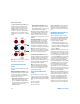
Protection Limits The Agilent 34450A 5½ Digital Multimeter provides protection circuitry to prevent damage to the instrument and to protect against the danger of electric shock, provided that the Protection Limits are not exceeded. To ensure safe operation of the instrument, do not exceed the Protection Limits shown on the front panel, as defined below: E A B C D Note: The front-panel terminals and current protection fuse are shown above.
WA R N I N G • Do not defeat the power cord safety ground feature. Plug in to a grounded (earthed) outlet. • Do not use the instrument in any manner that is not specified by the manufacturer. • To avoid electric shock or injury, do not operate the multimeter without panels or case in place. • Do not substitute parts or modify the instrument to avoid the danger of introducing additional hazards.
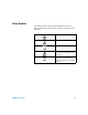
Environmental Conditions This instrument is designed for indoor use and in an area with low condensation. The table below shows the general environmental requirements for the instrument.
Waste Electrical and Electronic Equipment (WEEE) Directive 2002/96/EC This instrument complies with the WEEE Directive (2002/96/EC) marking requirement. This affixed product label indicates that you must not discard this electrical/electronic product in domestic household waste. Product Category: With reference to the equipment types in the WEEE directive Annex 1, this instrument is classified as a “Monitoring and Control Instrument” product.
Additional Notices The Agilent 34450A is provided with an Agilent 34138A Test Lead Set, described below. Test Lead Ratings Test Leads - 1000 V, 15 A Fine Tip Probe Attachments - 300 V, 3 A Mini Grabber Attachment - 300 V, 3 A SMT Grabber Attachments - 300 V, 3 A Operation The Fine Tip, Mini Grabber, and SMT Grabber attachments plug onto the probe end of the Test Leads. Maintenance If any portion of the Test Lead Set is worn or damaged, do not use. Replace with a new Agilent 34138A Test Lead Set.
Declaration of Conformity (DoC) The Declaration of Conformity (DoC) for this instrument is available on the Web site. You can search the DoC by its product model or description. http://regulations.corporate.agilent.com/DoC/search.htm NOTE 34450A Service Guide If you are unable to search for the respective DoC, please contact your local Agilent representative.
THIS PAGE HAS BEEN INTENTIONALLY LEFT BLANK.
Table of Contents 1 Performance Tests and Calibration Calibration Overview 2 Closed-case calibration 2 Agilent Technologies calibration services Calibration interval 3 Time required for calibration 3 Automating calibration procedures 3 Recommended Test Equipment 2 4 Test Considerations 5 Input connections 6 Performance Verification Tests Overview Self test 7 Quick performance check 8 Performance Verification Tests 9 Zero offset verification 9 Gain verification 11 DC current gain verification test 12 Oh
Zero adjustment 29 Gain adjustments 29 DC voltage gain adjustment procedure DC current gain adjustments procedure AC voltage gain adjustment procedure AC current gain adjustment procedure Ohms gain adjustment procedure 36 Capacitance gain adjustment procedure Frequency gain adjustment procedure Finishing the adjustments 39 Calibration Message 40 To read the calibration count Calibration Errors 2 38 39 40 41 Disassembly and Repair Operating Checklist 44 Types of Services Available 45 Repackaging for
List of Tables Table 1-1 Table 1-2 Table 1-3 Table 1-4 Table 1-5 Table 1-6 Table 1-7 Table 1-8 Table 1-9 Table 1-10 Table 1-11 Table 1-12 Table 1-13 Table 1-14 Table 1-15 Table 1-16 Table 1-17 Table 2-1 Table 2-2 34450A Service Guide Recommended test equipment 4 Zero offset verification test 10 DC voltage gain verification test 12 DC current gain verification test 13 Ohms gain verification test 15 Frequency gain verification test 16 AC volts verification test 17 AC current verification test 20 Capacitance
THIS PAGE HAS BEEN INTENTIONALLY LEFT BLANK.
Agilent 34450A 5½ Digit Multimeter Service Guide 1 Performance Tests and Calibration Calibration Overview 2 Recommended Test Equipment 4 Test Considerations 5 Performance Verification Tests Overview 7 Performance Verification Tests 9 Calibration Security 23 Calibration Process 26 Adjustments 29 Calibration Message 40 Calibration Errors 41 This chapter contains performance test procedures and calibration procedures.
1 Performance Tests and Calibration Calibration Overview Calibration Overview NOTE . Make sure you have read “Test Considerations” on page 5 before calibrating the instrument. Closed-case calibration The instrument features closed- case electronic calibration. No internal mechanical adjustments are required. The instrument calculates correction factors based upon the input reference value you set.
Performance Tests and Calibration Calibration Overview 1 Calibration interval A one year interval is adequate for most applications. Accuracy specifications are warranted only if adjustment is made at regular calibration intervals. Accuracy specifications are not warranted beyond the one year calibration interval. Agilent does not recommend extending calibration intervals beyond two years for any application. Time required for calibration The 34450A can be automatically calibrated under computer control.
1 Performance Tests and Calibration Recommended Test Equipment Recommended Test Equipment The test equipment recommended for the performance verification and adjustment procedures is listed in Table 1- 1 below. If the exact instrument is not available, substitute calibration standards of equivalent accuracy. A suggested alternate method would be to use the Agilent 3458A 8½ Digit Digital Multimeter to measure less accurate yet stable sources.
Performance Tests and Calibration Test Considerations 1 Test Considerations Errors may be induced by AC signals present on the input leads during a self test. Long test leads can also act as an antenna causing pick- up of AC signals. For optimum performance, all procedures should comply with the following recommendations: • Assure that the calibration ambient temperature is stable and between 18 °C and 28 °C. Ideally the calibration should be performed at 23 °C ±1 °C.
1 Performance Tests and Calibration Test Considerations Input connections Test connections to the instrument are best accomplished using the dual banana plug with copper wire shorted between two terminals for low- thermal offset measurement. Shielded, twisted- pair, PTFE interconnect cables of minimum length are recommended between the calibrator and the multimeter. Cable shields should be earth ground referenced.
Performance Tests and Calibration Performance Verification Tests Overview 1 Performance Verification Tests Overview Use the performance verification tests to verify the measurement performance of the instrument. The performance verification tests use the instrument's specifications listed in the Agilent 34450A User's Guide, Chapter 4, Specifications. You can perform four different levels of performance verification tests: • Self test.
1 Performance Tests and Calibration Performance Verification Tests Overview • If all tests pass, you have a high confidence (~90%) that the instrument is operational. • You can initiate a more complete self test by sending the *TST? command to the instrument. This command returns a "+0" if all the self- tests pass, or a "+1" if a failure occurred. This command may take up to 10 seconds to complete. You may need to set an appropriate interface time- out value.
Performance Tests and Calibration Performance Verification Tests 1 Performance Verification Tests The performance verification tests are recommended as acceptance tests when you first receive the instrument. The acceptance test results should be compared against the one year test limits. After acceptance, you should repeat the performance verification tests at every calibration interval. If the instrument fails performance verification, adjustment or repair is required.
1 Performance Tests and Calibration Performance Verification Tests Zero offset verification test 1 Connect the shorting plug to the HI and LO input terminals. (see “Input connections” on page 6). Leave the current inputs open. 2 Select each function and range in the order shown in the table below. Make a measurement and observe the result.
Performance Tests and Calibration Performance Verification Tests 1 Table 1-2 Zero offset verification test Step Function[1] Range Short Ohms 100 Ω ±8 mΩ[2] Short 1 kΩ ±80 mΩ[2] Short 10 kΩ Short 100 kΩ ±5 Ω Short 1 MΩ ±50 Ω Short 10 MΩ ±500 Ω Short 100 MΩ ±5 kΩ Quick Check Q Error from Nominal 1 year ±500 mΩ[2] [1] Select 5½ digit (slow mode) measurement resolution [2] Specifications are for 4-W or 2-W ohms function using the Null math function enabled to eliminate lead resista
1 Performance Tests and Calibration Performance Verification Tests 2 Select each function and range in the order shown below. Provide the input shown in the table below. 3 Make a measurement and observe the result. Compare measurement results to the appropriate test limits shown in the table.
Performance Tests and Calibration Performance Verification Tests 1 For range ≥ 1 A , Input < 3A For range ≥ 1 A , Input ≥ 3A 2 Select each function and range in the order shown below. Provide the input shown in the table below. 3 Make a measurement and observe the result. Compare measurement results to the appropriate test limits shown in the table. (Be certain to allow for appropriate source settling when using the Fluke 5520A.
1 Performance Tests and Calibration Performance Verification Tests Table 1-4 DC current gain verification test Input Function[1] Range Quick Check Error from Nominal 1 year 1A 1A Q ±1.15 mA 10 A 10 A ±25.
Performance Tests and Calibration Performance Verification Tests 1 4- W resistance with compensation (For range 100 Ω ~ 100 kΩ ) 4- W resistance without compensation (For range 1 MΩ ~ 100 MΩ ) 2 Select the 4- W Ohms or 2- W Ohms function. 3 Select each range in the order shown below. Provide the resistance value indicated. Compare measurement results to the appropriate test limits shown in the table. (Be certain to allow for appropriate source settling.
1 Performance Tests and Calibration Performance Verification Tests [1] Select Slow Mode 5½ digit measurement resolution [2] Specifications are for 4-wire for 2- wire ohms function using the Null math function enabled to eliminate lead resistance. Without Null, add 0.2 Ω additional error.
Performance Tests and Calibration Performance Verification Tests 1 AC voltage verification test Configuration: AC Volts (CONFigure[:VOLTage]:AC) 1 Connect the calibrator to the front panel HI and LO input terminals as shown in the figure below: 2 Select the AC voltage function. 3 Select each range in the order shown below. Provide the indicated input voltage and frequency. Compare measurement results to the appropriate test limits shown in the table. (Be certain to allow for appropriate source settling.
1 Performance Tests and Calibration Performance Verification Tests Table 1-7 AC volts verification test Vrms Input Frequency Function[1] Range Quick Check Error from Nominal 1 Year Q ±3 mV 1V 1 kHz 1V 1V 10 kHz 1V ±3 mV 1V 30 kHz 1V ±18 mV 1V 100 kHz 1V ±33 mV 10 V 20 Hz 10 V ±0.11 V 10 V 45 Hz 10 V ±30 mV 10 V 1 kHz 10 V ±30 mV 10 V 10 kHz 10 V ±30 mV 10 V 30 kHz 10 V 10 V 100 kHz 10 V ±0.33 V 100 V 45 Hz 100 V ±0.3 V 100 V 1 kHz 100 V ±0.
Performance Tests and Calibration Performance Verification Tests 1 AC current verification test Configuration: AC current (CONFigure:CURRent:AC) 1 Connect the calibrator to the front panel HI and LO input terminals as shown in the figure below: For range ≤ 100 mA For range ≥ 1 A , Input < 3A 34450A Service Guide 19
1 Performance Tests and Calibration Performance Verification Tests For range ≥ 1 A , Input ≥ 3A 2 Select the AC current function. 3 Select each range in the order shown below. Provide the input current and frequency indicated. Compare measurement results to the appropriate test limits shown in the table. (Be certain to allow for appropriate source settling.
Performance Tests and Calibration Performance Verification Tests 1 Table 1-8 AC current verification test Input Input Frequency Function[1] Range Quick Check Error from Nominal 1 year 1A 1 kHz 1A ±6 mA 1A 5 kHz 1A ±22 mA 10 A 45 Hz 10 A ±60 mA 10 A 1 kHz 10 A ±60 mA 2A 5 kHz 10 A ±60 mA [1] Select Slow Mode 5½ digit measurement resolution Q= Quick performance verification test points 34450A Service Guide 21
1 Performance Tests and Calibration Performance Verification Tests Capacitance performance verification test Configuration: Capacitance (CONFigure:CAPacitance) 1 Connect the calibrator to the front panel HI and LO input terminals as shown in the figure below: 2 Select the Capacitance function. 3 Select each range in the order shown below. Provide the indicated input voltage and frequency. Compare measurement results to the appropriate test limits shown in the table.
Performance Tests and Calibration Calibration Security 1 Calibration Security The calibration security code prevents accidental or unauthorized adjustments to the instrument. When you first receive your instrument, it is secured. Before you can adjust the instrument, you must unsecure it by entering the correct security code (see “Unsecuring the instrument for calibration” on page 24). The security code is set to AT34450 when the instrument is shipped from the factory.
1 Performance Tests and Calibration Calibration Security Unsecuring the instrument for calibration Before you can adjust the instrument, you must unsecure it by entering the correct security code. The security code is set to AT34450 when the instrument is shipped from the factory. The security code is stored in non- volatile memory, and does not change when power has been off or after a Factory Reset (*RST command).
Performance Tests and Calibration Calibration Security 1 Example 3 Assume the calibration security code has been set to ATB1 through remote interface. The first two characters (AT) are ignored. The B is represented by a zero. The “1” is still used and trailing zeros fill in the remaining characters. Use this code to unsecure: 01000 To unsecure the instrument from the front panel 1 Press followed by to enter the Utility menu.
1 Performance Tests and Calibration Calibration Process Calibration Process The following general procedure is the recommended method to complete a full instrument calibration. 1 Read “Test Considerations” on page 5. 2 Perform the verification tests to characterize the instrument (incoming data). 3 Unsecure the instrument for calibration (see “Calibration Security” on page 23). 4 Perform the adjustment procedures (see “Adjustments” on page 29). 5 Secure the instrument against calibration.
Performance Tests and Calibration Calibration Process 1 Using the front panel for adjustments This section describes the process used to perform adjustments from the front panel. Refer to the 34450A Programmer's Reference online help for remote interface commands. Selecting the Adjustment Mode 1 Press > to enter the Utility menu. 2 Select CALIBRATION and press to enter Calibration menu. 3 Select CAL MODE and press to enter Calibration mode.
1 Performance Tests and Calibration Calibration Process CAUTION 28 If you abort a calibration in progress, all calibration constants for the selected function range are lost. If power is turned off when the instrument is attempting to write new calibration constants to EEPROM, all calibration constants for the selected function range may also lost. Typically, upon re–applying power, the instrument will report Calibration Corrupt in the Questionable Data Register.
Performance Tests and Calibration Adjustments 1 Adjustments You will need a test input cable and connectors set, and a shorting plug to adjust the instrument (see “Input connections” on page 6). NOTE After each adjustment finishes successfully, the display briefly shows PASS at the status box. If the calibration fails, the multimeter beeps, the display shows FAIL at the status box. In the event of a calibration failure, correct the problem and repeat the procedure.
1 Performance Tests and Calibration Adjustments CAUTION Never turn off the instrument during a gain adjustment. This may cause calibration memory for the present function to be lost. Valid gain and frequency compensation input values. Gain adjustment can be accomplished using the preset calibration points. Table 1-10 Valid gain and frequency compensation input values Function Range Valid Amplitude Input Values DC voltage 1V 100 mV, 10 V, 100 V, 1000 V (0, ±0.2, ± 0.4, ± 0.6, ± 0.8, ± 1, ± 1.
Performance Tests and Calibration Adjustments 1 Calibration mode: DC voltage 1 Apply the input signal shown in the Calibration Point box. 2 Press to start the adjustment. The Status box displays CALIBRATING indicates the calibration is in progress. • Successful completion of each adjustment value is indicated by a message in the Status box showing PASS. • An adjustment failure is indicated by a message in the Status box showing FAIL.
1 Performance Tests and Calibration Adjustments DC current gain adjustments procedure Review the “Test Considerations” on page 5 and “Gain adjustment considerations” on page 29 sections before beginning this procedure. Calibration mode: DC current 1 Press or to select the calibration range. 2 The Measurement box displays the uncalibrated value and the Calibration Point box displays the reference value. 3 Apply the input signal shown in the Calibration Point box, Table 1- 12 below.
Performance Tests and Calibration Adjustments 1 Table 1-12 DC current gain adjustment Input Function Range 2 mA, 7 mA, 10 mA, –2 mA, –7 mA, –10 mA 10 mA 20 mA, 70 mA, 100 mA, –20 mA, –70 mA, –100 mA 100 mA Caution: Connect calibrator to multimeter’s 10 A and LO terminals before applying 1 A and 10 A range 0.2 A, 0.7 A, 1 A, –0.2 A, –0.7 A, –1 A 1A 2 A, 7 A, 10 A, –2 A, –7 A, –10 A 10 A [1] Cal Item OPEN only calibrated once during DC current gain adjustment procedure.
1 Performance Tests and Calibration Adjustments • An adjustment failure is indicated by a message in the Status box showing FAIL. Check the input value, range, function, and entered adjustment value to correct the problem and repeat the adjustment step. 5 Repeat step 1 through 4 for each gain adjustment point shown in the preset calibration point box. 6 When the calibration has been completed for the selected range, the status box shows DONE, and the value in the Calibration Range box flashes.
Performance Tests and Calibration Adjustments 1 AC current gain adjustment procedure Review the “Test Considerations” on page 5 and “Gain adjustment considerations” on page 29 sections before beginning this procedure. AC voltage gain adjustment for 100 mV range calibration has to be done prior to performing the AC current gain adjustments procedure. Calibration Mode: AC current 1 Press or to select the calibration range.
1 Performance Tests and Calibration Adjustments Table 1-14 AC current gain adjustment Input Instrument Settings Current, rms Frequency Function Range Caution: Connect calibrator to multimeter’s 10 A and LO terminals before applying 1A and 10 A range. 0.1 A, 0.7 A, 1 A 1 kHz 1A 1 A, 7 A, 10 A 1 kHz 10 A Ohms gain adjustment procedure Review the “Test Considerations” on page 5 and “Gain adjustment considerations” on page 29 sections before performing this procedure.
Performance Tests and Calibration Adjustments 1 6 When the calibration has been completed for the selected range, the status box shows DONE, and the value in the Calibration Range box flashes. 7 Verify the Ohms gain adjustments using the “Ohms gain verification test” on page 14. Table 1-15 Ohms gain adjustment Input Function Range 0 Ω[1] 2-W Resistance/4-W Resistance Any 20 Ω, 70 Ω, 100 Ω 100 Ω 0.2 kΩ, 0.7 kΩ, 1 kΩ 1k Ω 2 kΩ, 7 kΩ, 10 kΩ 10 kΩ 20 kΩ, 70 kΩ, 100 kΩ 100 kΩ 0.2 MΩ, 0.
1 Performance Tests and Calibration Adjustments Capacitance gain adjustment procedure Review the “Test Considerations” on page 5 and “Gain adjustment considerations” on page 29 sections before beginning this procedure. Calibration Mode: Capacitance 1 Apply the input signal shown in the Calibration Point Box. 2 Press to start the adjustment. The Status box displays CALIBRATING indicates the calibration is in progress.
Performance Tests and Calibration Adjustments 1 Frequency gain adjustment procedure Review the “Test Considerations” on page 5 and “Gain adjustment considerations” on page 29 sections before beginning this procedure. Calibration Mode: Frequency 1 Apply the input signal shown in the Calibration Point Box. 2 Press to start the adjustment. The Status box displays CALIBRATING indicates the calibration is in progress.
1 Performance Tests and Calibration Calibration Message Calibration Message The instrument allows you to store a message in calibration memory. For example, you can store such information as the date when the last calibration was performed, the date when the next calibration is due, the instrument's serial number, or even the name and phone number of the person to contact for a new calibration. The calibration message may contain up to 40 characters.
Performance Tests and Calibration Calibration Errors 1 Calibration Errors The following errors indicate failures that may occur during a calibration.
1 Performance Tests and Calibration Calibration Errors THIS PAGE HAS BEEN INTENTIONALLY LEFT BLANK.
Agilent 34450A 5½ Digit Multimeter Service Guide 2 Disassembly and Repair Operating Checklist 44 Types of Services Available 45 Repackaging for Shipment 46 Cleaning 46 To Replace the Power Line Fuse 47 To Replace a Current Input Fuse 48 To Verify your Device License 49 Self Test Errors 50 Electrostatic Discharge (ESD) Precautions 51 Mechanical Disassembly 52 Replaceable Parts 58 Rack Mounting 60 This chapter will help you troubleshoot a failing multimeter.
2 Disassembly and Repair Operating Checklist Operating Checklist Before returning your multimeter to Agilent for service or repair check the following items: Is the multimeter inoperative? q Verify the power line voltage setting. q Verify the power line fuse is installed. q Verify that the power cord is connected to the multimeter and to AC line power. q Verify the front panel power switch is depressed.
Disassembly and Repair Types of Services Available 2 Types of Services Available If your instrument fails during the warranty period, Agilent Technologies will repair or replace it under the terms of your warranty. After your warranty expires, Agilent offers repair services at competitive prices. Extended service contracts Many Agilent products are available with optional service contracts that extend the covered period after the standard warranty expires.
2 Disassembly and Repair Repackaging for Shipment Repackaging for Shipment If the unit is to be shipped to Agilent for service or repair, be sure to: • Attach a tag to the unit identifying the owner and indicating the required service or repair. Include the model number and full serial number. • Place the unit in its original container with appropriate packaging material for shipping. • Secure the container with strong tape or metal bands.
Disassembly and Repair To Replace the Power Line Fuse 2 To Replace the Power Line Fuse The power line fuse is located within the multimeter’s fuse- holder assembly on the rear panel. The multimeter is shipped from the factory with a power- line fuse installed. The supplied fuse is a time- delay, 0.25 A 250 V Time- delay 1.9 Ohm 20.5×5.2×5.2mm glass- tube fuse, Agilent part number 2110- 1533. If you have determined that the fuse is faulty, replace it with one of the same size and rating.
2 Disassembly and Repair To Replace a Current Input Fuse To Replace a Current Input Fuse Both the 100 mA and the 10 A current input terminals are fuse protected. The fuse for the 100 mA input terminal is located on the rear panel (refer to Agilent 34450A User’s Guide, Chapter 1). The fuse is a 0.4A 500 V fast acting 32×6.3×6.3 mm fuse, Agilent part number 21101503. If you have determined that the fuse is faulty, replace it with one of the same size and rating.
Disassembly and Repair To Verify your Device License 2 To Verify your Device License 1 Go to page 2 of the Utility Menu as shown below : 2 If you have purchased the GPIB option, the GPIB Option displays ON. 3 If you have purchased the 50k memory option, the 50k Memory option displays ON. 4 If you have not purchased any option, the GPIB Option and 50K Memory display OFF.
2 Disassembly and Repair Self Test Errors Self Test Errors The 34450A self test (see the *TST? command) performs a series of tests on the instrument hardware. Any failure of these tests will generate a SCPI error number - 330, with additional test failure information. Refer to the Agilent 34450A Programmer’s Helpfile for more information. NOTE On the remote interface, a self–test failure will generate SCPI error –330 and a supplemental message indicating one of the test numbers shown below.
Disassembly and Repair Electrostatic Discharge (ESD) Precautions 2 Electrostatic Discharge (ESD) Precautions Almost all electrical components can be damaged by electrostatic discharge (ESD) during handling. Component damage can occur at electrostatic discharge voltages as low as 50 V. The following guidelines will help prevent ESD damage when servicing the instrument or any electronic device. • Disassemble instruments only in a static- free work area. • Use a conductive work area to reduce static charges.
2 Disassembly and Repair Mechanical Disassembly Mechanical Disassembly For procedures in this manual, the following tools are required for disassembly: • T20 Torx driver (most disassembly) WA R N I N G SHOCK HAZARD. Only service–trained personnel who are aware of the hazards involved should remove the instrument covers. To avoid electrical shock and personal injury, make sure to disconnect the power cord from the instrument before removing the covers.
Disassembly and Repair Mechanical Disassembly 2 3 Remove the instrument bumpers. Pull from a corner and stretch the bumpers off the instrument. 4 Remove the rear bezel. Loosen the two captive screws in the rear bezel and remove the rear bezel.
2 Disassembly and Repair Mechanical Disassembly 5 Remove the cover. Remove the screw in the bottom of the cover and slide the cover off the instrument. Front panel removal 6 Remove the two screws holding the front panel.
Disassembly and Repair Mechanical Disassembly 2 7 Disconnect the ribbon cable connectors from the front panel.
2 Disassembly and Repair Mechanical Disassembly 9 Disconnect the fuse wire as shown in the figure below: 10 There is now enough space to allow the side of the front panel to be pried from the chassis and removed as an assembly.
Disassembly and Repair Mechanical Disassembly 2 Front panel 1 Remove the keyboard and display assembly. Remove the screw from the circuit board gently to disengage from the tabs. Lift the keyboard and display assembly from the plastic housing. 2 Pull the rubber keypad from the plastic housing.
2 Disassembly and Repair Replaceable Parts Replaceable Parts This section contains information for ordering replaceable parts for your 34450A. Table 2- 2 on page 58 includes a brief description of each replaceable part with its corresponding part number. NOTE You can find the latest 34450A support parts list at Agilent Test & Measurement Parts Catalog: http://www.agilent.
Disassembly and Repair Replaceable Parts 2 Table 2-2 Replaceable parts list 34450A Service Guide Part Number Description 2110-1503 Fuse 0.4 A, 500 V Fast Acting 32 × 6.3 2110-1533 Fuse 0.25 A 250 V Time-delay 1.9 Ohm 20.5 × 5.2 × 5.2 mm glass-tube × 6.
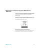
2 Disassembly and Repair Rack Mounting Rack Mounting You can mount the multimeter in a standard 19- inch rack cabinet using one of three optional kits shown below. Instructions and mounting hardware are included with each rack- mounting kit. Any Agilent Technologies instrument of the same size can be rack- mounted beside the 34450A 5½ Digit Multimeter. NOTE You must remove the carrying handle (see page 52) and the front and rear bumpers (see page 53) before rack mounting the multimeter.
www.agilent.