Agilent 34980A Multifunction Switch/Measure Unit Service Guide Agilent Technologies
Notices © Agilent Technologies, Inc. 2006, 2011, 2012, 2013 Warranty Microsoft and Windows are U.S. registered trademarks of Microsoft Corporation. The material contained in this document is provided “as is,” and is subject to being changed, without notice, in future editions.
Additional Safety Notices The following general safety precautions must be observed during all phases of operation of this instrument. Failure to comply with these precautions or with specific warnings or instructions elsewhere in this manual violates safety standards of design, manufacture, and intended use of the instrument. Agilent Technologies assumes no liability of the customer’s failure to comply with the requirements.
iii
Front Panel at a Glance 1 2 3 4 5 6 7 8 9 10 11 12 13 WARNIN On/Standby switch WARNINGs.. This switch is standby only. To disconnect the mains from the instrument, remove the power cord.
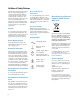
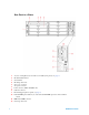
Rear Panel at a Glance 1 2 3 4 5 6 7 8 9 10 11 12 v Access to Analog Buses (shown with cover installed). For pinout, see page vi. Module installed in slot 1 Slot identifier Module ground screw Slot cover over slot 2 AC power connector LAN connector (10Base T/100Base Tx) USB 2.0 connector External trigger input. For pinout, see page vi. Internal DMM option mark. If you ordered the internal DMM option, the circle is marked black. IEEE 488.
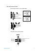
Rear Panel Connector Pinouts External Trigger/Alarms Connector (Male D-Sub) Input 5V 0V 6 9 1 5 Ext Trig Input / Chan Adv Input (Pin 6) > 1 μs Output Gnd (Pin 9) 3.3 V Chan Closed Output / VM Comp Output (Pin 5) 0V Approx.
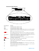
Annunciator Display Indicators Display Indicator LAN USB GPIB ABUS [1234] ERRO Rmt Safety Interlock Trig HO ALARM (H1234L) Definition Communicating with the 34980A over LAN. Communicating with the 34980A over USB. Communicating with the 34980A over GPIB. Analog Bus Connectivity. Normally, designated ABus connected on any module in mainframe. During scan, if ABus 1 and ABus 2 are indicated, they will be used at some point during the scan. An error has been generated and is in the error queue. Remote.
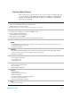
Front Panel Menu Reference This section gives an overview of the top two levels of menus that you access from the front panel. The menus are designed to automatically guide you through all parameters required to configure a particular function or operation. Store/Recall Store and recall instrument states • Store up to six instrument states in non-volatile memory • Assign a name to each storage location.
Advanced Available at a later firmware release Alarm • Select one of four alarms to report alarm conditions on the displayed channel • Configure a high limit, a low limit, or both for the displayed channel • Select the slope (rising or falling edge) for the four alarm output lines ix 34980A Service Guide
Instrument Rack Mounting Using the optional Agilent Y1130A Rack Mount Kit, you can mount the 34980A in a standard 19- inch rack cabinet. This kit includes rack mount brackets and associated hardware required to forward or reverse mount the instrument in the rack cabinet. • For forward rack mounting (34980A front panel facing the front of the cabinet), use the Agilent standard rack mount kit (part number 5063- 9214). For Agilent rack cabinets, use the E3663A Basic Rail Kit (sold separately).
425.6 mm (16.76 in) 367.7 mm (14.48 in) 101.9 mm (4.01 in) or 70.4 mm (2.
Contents Front Panel at a Glance iii Rear Panel at a Glance iv Rear Panel Connector Pinouts v Annunciator Display Indicators vi Front Panel Menu Reference vii Instrument Rack Mounting vii 1 Obtaining Service Operating Checklist 6 Types of Service Available 6 Repackaging for Shipment 7 Cleaning 7 Self Test Procedures 8 Electrostatic Discharge (ESD) Precautions 9 2 Specifications Multiplexer Module Specifications and Characteristics 12 Matrix Modules Specifications and Characteristics 14 GP Actuator Module
3 Calibration Procedures Agilent Technologies Calibration Services 44 Calibration Interval 44 Adjustment is Recommended 44 Time Required for Calibration 45 Automating Calibration Procedures 45 Recommended Test Equipment 46 Calibration Security 47 Calibration Message 48 Calibration Count 48 Calibration Process 49 Aborting a Calibration in Progress 49 Performance Verification Tests 50 Input Connections 52 DMM Test Considerations 53 Internal DMM Verification Tests 53 Optional AC Performance Verification Tests
4 Troubleshooting and Diagnostics Troubleshooting Hints 78 Power Supply 79 Product Firmware Updates 79 Instrument Errors 80 Error Numbers 82 Isolate a Problem with a Plug-In Module 90 Relay and FET Replacement 91 34921A 40-Channel Armature Multiplexer with Low Thermal Offset 34922A 70-Channel Armature Multiplexer 94 34923A 40/80-Channel Reed Multiplexer 96 34924A 70-Channel Reed Multiplexer 98 34925A 40/80-Channel Optically-Isolated FET Multiplexer 100 34931A Dual 4x8 Armature Matrix 102 34932A Dual 4x16 Ar
6 Replaceable Parts To Order Replaceable Parts 124 Backdating and Part Changes 124 Mainframe Replaceable Parts 125 34921A Replaceable Parts 126 34922A Replaceable Parts 126 34923A Replaceable Parts 127 34924A Replaceable Parts 127 34925A Replaceable Parts 127 34931A Replaceable Parts 128 34932A Replaceable Parts 129 34933A Replaceable Parts 130 34937A Replaceable Parts 130 34938A Replaceable Parts 130 34946A and 34947A Replaceable Parts 131 Vendor Addresses 131 7 Backdating 8 Diagrams 34921A Component Loca
Agilent 34980A Multifunction Switch/Measure Unit Service Guide 1 Obtaining Service Operating Checklist 6 Types of Service Available 6 Repackaging for Shipment 7 Cleaning 7 Self Test Procedures 8 Electrostatic Discharge (ESD) Precautions 9 Agilent Technologies 5
1 Obtaining Service Obtaining Service Operating Checklist Before returning your instrument to Agilent for service or repair check the following items: Is the instrument inoperative? q Verify that the power cord is connected to the instrument and to ac line power. q Verify the front panel power switch is depressed. Does the instrument fail self–test? q Remove all test connections to the instrument and run the self–test again.
Obtaining Service 1 Obtaining Repair Service (Worldwide) To obtain service for your instrument (in- warranty, under service contract, or post- warranty), contact your nearest Agilent Technologies Service Center. They will arrange to have your unit repaired or replaced, and can provide warranty or repair- cost information where applicable.
1 Obtaining Service Self Test Procedures Power–On Self–Test Each time the instrument is powered on, a subset of self–tests are performed. These tests check that the minimum set of logic and output hardware are functioning properly. Complete Self–Test To perform a complete self–test send the *TST? command. This command performs a complete self- test of the instrument and all installed plug- in modules and returns a pass/fail indication.
Obtaining Service 1 Electrostatic Discharge (ESD) Precautions Almost all electrical components can be damaged by electrostatic discharge (ESD) during handling. Component damage can occur at electrostatic discharge voltages as low as 50 volts. The following guidelines will help prevent ESD damage when servicing the instrument or any electronic device. • Disassemble instruments only in a static–free work area. • Use a conductive work area to reduce static charges.
1 10 Obtaining Service 34980A Service Guide
Agilent 34980A Multifunction Switch/Measure Unit Service Guide 2 Specifications Multiplexer Module Specifications and Characteristics 12 Matrix Modules Specifications and Characteristics 14 GP Actuator Module Specifications and Characteristics 16 RF and Microwave Module Specifications and Characteristics 17 34945A/34945EXT Module Specifications and Characteristics 19 34950A 64-channel Digital I/O Specifications and Characteristics 20 34951A 4-channel D/A Converter Specifications and Characteristics 22 3495
2 Specifications Multiplexer Module Specifications and Characteristics 34921A 34922A 34923A 34924A 34925A Channels/configurations 40 2-wire 20 4-wire 4-current 1.
Specifications 2 Multiplexer Module Specifications and Characteristics (continued) 34921A 34922A 34923A 34924A 34925A Bandwidth at terminal block [1] 45 MHz 25 MHz 45 MHz[2]/4 MHz 25 MHz[2]/4 10 MHz 1-wire MHz[4] 1 MHz N/A AC characteristics Crosstalk at terminal block (ch-ch) [1] 300 kHz 1 MHz 20 MHz 45 MHz –75 dB –75 dB –50 dB –40 dB –75 dB –75 dB –50 dB –75 dB –75 dB –50 dB –40 dB –75 dB –70 dB –45 dB Capacitance at terminal block HI-LO LO e
2 Specifications Matrix Modules Specifications and Characteristics 34931A 34932A 34933A 34934A Channels/configurations dual 4x8 8x8, 4x16 dual 4x16 8x16, 4x32 dual 4x8, 8x8 4x16, quad 4x8, 1-wire quad 4x32, 4x128, 8x64,16x32 Switch type Armature latching Armature latching Reed non-latching Reed non-latching Max volts ± 300 V [1] ± 300 V [1] ± 150 V peak [2] ± 100 V peak Max current (DC, AC RMS) Switch current Carry current 1 A 2A 1 A 2A 0.5 A[4]/0.05 A[7] 1.
2 Specifications Matrix Modules Specifications and Characteristics (continued) 34931A 34932A 34933A 34934A Bandwidth at terminal block [1] 30 MHz 30 MHz 30 MHz[2]/4 MHz [3] 2 MHz 1-wire 35 MHz 2-wire 15 MHz 1-wire Crosstalk at terminal block (ch-ch) [1] 300 kHz 1 MHz 20 MHz –65 dB –55 dB –30 dB –65 dB –55 dB –30 dB –65 dB –55 dB –40 dB –65 dB –55 dB –33 dB Capacitance at terminal block HI-LO LO - earth 50 pF 80 pF 50 pF 80 pF 80 pF 75 pF 45 pF 250 pF
2 Specifications GP Actuator Module Specifications and Characteristics 34937A 34938A Channels/configurations 28 Form C 4 Form A 20 Form A Switch type Armature, latching Armature, latching Max volts (DC, AC RMS) [1] Form C — 300 V Form A — 30 VDC/250 VAC 30 VDC/250 VAC Max current (DC, AC RMS) Form C —1 A switch (2 A carry) Form A — 5 A switch (8 A carry) 5 A switch (8 A carry) Power (W, VA) [2] Form C — 60 W Form A — 150 W 150 W Volt-Hertz limit 108 108 Offset voltage 3 V 3 V
2 Specifications RF and Microwave Module Specifications and Characteristics DC to 20 GHz [2] DC to 3 GHz 34941A 34942A 34946A 34947A Channels quad 1x4 quad 1x4 2 SPDT 3 SPDT Switch type 50 unterminated, 75 unterminated, 50 terminated latching relays latching relays 50 unterminated RF characteristics [1] Frequency range [1] DC to 3 GHz DC to 1.5 GHz DC to 4 GHz or DC to 20 GHz DC to 4 GHz or DC to 20 GHz Insertion loss (< 40°C/80% RH) [1] 100 MHz 1 GHz 3 GHz 0.
2 Specifications RF and Microwave Module Specifications and Characteristics (continued) DC to 20 GHz [2] DC to 3 GHz 34941A 34942A 34946A 34947A Switching characteristics Max volts [1] 30 V 30 V 7 V DC 7 V DC Max current 0.5A 0.
Specifications 2 34945A/34945EXT Module Specifications and Characteristics 34945EXT switch drive (64 channels, low side drive mode) Driver off voltage (max) 30V Driver off leakage current 500 A Driver on current (max) 600 mA Driver on voltage (max) 0.5 V @ 600 mA 34945EXT switch drive (64 channels, TTL drive mode) Hi output voltage 3 V @ Iout = 2 mA Lo output voltage 0.4 V @ Iin = 20 mA Lo input Current 20 mA 34945EXT position indicator sense inputs Channels 64 Lo input voltage (max) 0.
2 Specifications 34950A 64-channel Digital I/O Specifications and Characteristics Digital input/output characteristics Eight 8-bit channels: 8 bits wide, input or output, non-isolated Vin 0 V – 5 V [1] Vout 1.66 V – 5 V [1] Iout (max) 24 mA [2] Frequency (max) 10 MHz [3] Iload (max) 400 mA trise + tfall Output (typ) 6 ns [4] 10K +5V Vcc +5.1V OE DOUT VREF Zo = 10 2.5 pF EN Rpullup 14.7 26.
Specifications 2 34950A 64-channel Digital I/O Specifications and Characteristics (continued) Handshake lines Vin 0 V – 5 V [1] Vout 1.
2 Specifications 34951A 4-channel D/A Converter Specifications and Characteristics General specifications Maximum update rate 200 kHz point-to-point Monotonic to 16-bits Isolation > 80 VDC/AC peak (chan-to-chassis or chan-to-chan) Synchronization Software commands or external trigger Internal/external CLK accuracy 100 ppm AC accuracy Not specified DC voltage Amplitude ± 16 V up to 10 mA Resolution 16-bits = 500 V Amplitude accuracy (DC) ± (0.05% + 3.
Specifications 2 34951A 4-channel D/A Converter Specifications and Characteristics (continued) Phase-locking I/O trigger characteristics Trigger input Input level TTL compatible (3.3 V logic, 5 V tolerant) Slope Rising or falling, selectable Pulse width > 100 nS Input impedance > 10 k, DC coupled Trigger output Level TTL compatible into 1 k(3.3 V logic) Output impedance 50 typical Clock input Input level TTL compatible (3.
2 Specifications 34952A Multifunction Module Specifications and Characteristics Digital input/output characteristics Four 8-bits channels, 8 bits wide, input or output, non-isolated Vin(L) < 0.8 V (TTL) Vin(H) > 2.0 V (TTL) Vout(L) < 0.8 V @ Iout = –400 mA Vout(H) > 2.
Specifications 2 34959A Breadboard Module Specifications and Characteristics General specifications Maximum module power dissipation 6 W Power available 12 V regulation no load to full load 5 V regulation no load to full load Maximum power from 12 V Maximum power from 5 V 10% 5% 6 W 1W Relay drives 28, sink up to 100 mA GPIO ports 34980A Service Guide Channel 1 and 2 8 configure bits as input or output Channel 3 3 output bits Dimensions (L x W x H) 5.4 x 7.5 x 0.
2 Specifications Internal DMM Specifications and Characteristics DC and Resistance Specifications DMM accuracy ± (% of reading + % of range). Includes measurement error, switching error[1], and transducer conversion error. Test Current or 24 hour [2,3] Burden Voltage Tcal ± 1 °C Function Range [4] DC voltage (with 34921A/ 22A/25A/31A/32A)[6] Input impedance = Hi-Z 10 V range and below 100.0000 mV 1.000000 V 10.00000 V 100.0000 V 300.0000 V Resistance [5] 100.0000 1mA 1.
Specifications 2 AC Specifications ±(% of reading + % of range) DMM accuracy ± (% of reading + % of range). Includes measurement error, switching error[1], and transducer conversion error. Function Range [4] Frequency 24 hour [2,3] Tcal ± 1 °C 90 days Tcal ± 5 °C 1 year Tcal ± 1 °C Temperature coefficient Tcal ± 5 °C True RMS AC voltage [5] 100.0000 mV to 100.
2 Specifications Additional Low Frequency Error for ACV, ACI (% of reading) Frequency AC Filter Slow AC Filter Medium AC Filter Fast – – 0.73 0.22 0.18 0 0.74 0.22 0.06 0.01 0 0 0 0 0 0 0 0 10 Hz – 20 Hz 20 Hz – 40 Hz 40 Hz – 100 Hz 100 Hz – 200 Hz 200 Hz – 1 kHz >1 kHz Additional Error for Frequency, Period (% of reading) Aperture (Digits) Frequency 1 second (6 digits) 0.1 seconds (5 digits) 0.01 seconds (4 digits) 0 0 0 0 0 0 0 0.12 0.17 0.2 0.06 0.03 0.01 0 0.12 0.17 0.2 0.21 0.21 0.
2 Specifications Typical System Speeds Measurements made on a 3.2 GHz PC running VB6 in Windows XP Professional. Single Channel Reading Time (in msec) Direct Measurements – direct to I/O (includes switch, measure time, and I/O time) Direct Measurment to Memory (GPIB) Single Channel [1, 2] GPIB USB 2.0 LAN (w/VXI 11) Measurement into memory Single Channel, DCV 2.83 ms 3.14 ms 4.57 ms 1.9 ms Single Channel, ACV 5.00 ms 5.35 ms 5.75 ms 4 ms Single Channel, Ohms 2.91 ms 3.14 ms 4.
2 Specifications Single Channel Measurement Rates — DMM Reading Rates [1, 2] Function Resolution DCV 4-1/2 digits (0.02 plc) 5-1/2 digits (1 plc) 6-1/2 digits (10 plc) 3000 59 6 2-wire Resistance 4-1/2 digits (0.02 plc) 5-1/2 digits (1 plc) 6-1/2 digits (10 plc) 2000 58 6 Thermocouple (0.02 plc) 0.1°C (1 plc) 2000 59 RTD/Thermistor 1°C (0.02 plc) 0.1°C (1 plc) 0.
2 Specifications Data Out of Memory to LAN, USB, or GPIB Data transfer rate with 1000 channel blocks. GPIB rdgs/sec USB 2.0 rdgs/sec LAN (w/VXI 11)[1] rdgs/sec Readings 2560 2400 3542 Readings with Timestamp 1304 1230 1826 Readings with all Format Options ON 980 926 1361 [1] LAN large block throughput rate is increased by approximately 30% using LAN sockets.
2 Specifications Internal DMM Measurement Characteristics (continued) Frequency and period Measurement method Reciprocal counting technique Voltage ranges Same as AC voltage function Gate time 1s, 100 ms, or 10 ms Measurement time-out Selectable 3 Hz, 20 Hz, 200 Hz LF limit Measurement Consideration All frequency counters are susceptible to error when measuring low-voltage, low-frequency signals. Shielding inputs from external noise pickup is critical for minimizing measurement errors.
2 Specifications Internal DMM Measurement Characteristics (continued) DC Operating Characteristics [1] Function DCV[4], DCI, and Resistance (10 k) Digits [2] 6½ 6½ 5½ 5½ 4½ Auto Zero OFF Operation Following instrument warm-up at calibration temperature ±1°C and <10 minutes, add 0.0002% range additional error +5 µV. (For 300 VDC, instead of 0.0002% of range, use 0.
2 Specifications System Specifications and Characteristics Scanning inputs Analog 34921A, 34922A, 34923A, 34924A, and 34925A multiplexer channels Digital 34950A/52A digital in and totalize Scan triggering Source Interval, external, button press, software, or on monitor channel alarm Scan count 1 to 50,000 or continuous Scan interval 0 to 99 hours; 1 ms step size Channel delay 0 to 60 seconds per channel; 1 ms step size External trig delay < 2 ms.
Specifications 2 System Specifications and Characteristics (continued) General specifications Power supply Universal 100 V to 240 V ±10% Power line frequency 50 – 60 Hz ±10% automatically sensed Power consumption 150 VA Operating environment Full accuracy for 0°C to 55°C Full accuracy to 80% R.H. at 40°C IEC 60664-1 pollution degree 1 Storage environment –40°C to 70°C [1] Mainframe dimensions 133H x 426W x 341D mm (5.25” x 16.8” x 14”) Full rack, 3 units high Mainframe weight 8.8 kg (19.
2 Specifications Product Dimensions 64.6 mm (2.54 in) 425.6 mm (16.76 in) 68.2 mm (2.68 in) 367.7 mm (14.48 in) M4.0 x 0.7 Thread 4 Places 22.4 mm (0.88 in) 2X 88.85 mm (3.50 in) 74.26 mm (2.92 in) 128.8 mm (5.07 in) 2X 93.6 mm (3.68 in) 5.5 mm (0.22 in) SQ M3.5 x 0.6 Thread 4 Places 404.0 mm (15.
2 Specifications To Calculate Total DMM Measurement Error Each specification includes correction factors which account for errors present due to operational limitations of the optional internal DMM. This section explains these errors and shows how to apply them to your measurements. Refer to “Interpreting Internal DMM Specifications" on page 39, to get a better understanding of the terminology used and to help you interpret the internal DMM’s specifications.
2 Specifications Understanding the “% of range“ Error The range error compensates for inaccuracies that result from the function and range you select. The range error contributes a constant error, expressed as a percent of range, independent of the input signal level. The following table shows the range error applied to the DMM’s 24- hour dc voltage specification. Range Input Level Range Error (% of range) Range Error voltage 10 Vdc 10 Vdc 10 Vdc 10 Vdc 1 Vdc 0.1 Vdc 0.0004 0.0004 0.
2 Specifications Interpreting Internal DMM Specifications This section is provided to give you a better understanding of the terminology used and will help you interpret the internal DMM’s specifications. Number of Digits and Overrange The “number of digits” specification is the most fundamental, and sometimes, the most confusing characteristic of a instrument. The number of digits is equal to the maximum number of “9’s” the instrument can measure or display. This indicates the number of full digits.
2 Specifications Accuracy Accuracy is a measure of the “exactness” to which the internal DMM’s measurement uncertainty can be determined relative to the calibration reference used. Absolute accuracy includes the Internal DMM’s relative accuracy specification plus the known error of the calibration reference relative to national standards (such as the U.S. National Institute of Standards and Technology).
Specifications 2 Configuring for Highest Accuracy Measurements The measurement configurations shown below assume that the internal DMM is in its Factory Reset state. It is also assumed that manual ranging is enabled to ensure proper full scale range selection. DC Voltage, DC Current, and Resistance Measurements: • Set the resolution to 6 digits (you can use the 6 digits slow mode for further noise reduction).
2 42 Specifications 34980A Service Guide
Agilent 34980A Multifunction Switch/Measure Unit Service Guide 3 Calibration Procedures Agilent Technologies Calibration Services 44 Calibration Interval 44 Adjustment is Recommended 44 Time Required for Calibration 45 Automating Calibration Procedures 45 Recommended Test Equipment 46 Calibration Security 47 Calibration Message 48 Calibration Count 48 Calibration Process 49 Aborting a Calibration in Progress 49 Performance Verification Tests 50 Input Connections 52 DMM Test Considerations 53 Inte
3 Calibration Procedures Calibration Procedures This manual contains procedures for verification of the instrument’s performance and adjustment (calibration). Closed-Case Electronic Calibration The instrument features closed- case electronic calibration. No internal mechanical adjustments are required. The instrument calculates correction factors based upon the input reference value you set. The new correction factors are stored in non- volatile memory until the next calibration adjustment is performed.
3 Calibration Procedures Time Required for Calibration The 34980A can be automatically calibrated under computer control. With computer control you can perform the complete calibration procedure and performance verification tests in less than 30 minutes once the instrument is warmed- up (see “DMM Test Considerations" on page 53). Automating Calibration Procedures You can automate the complete verification and adjustment procedures outlined in this manual.
3 Calibration Procedures Recommended Test Equipment The test equipment recommended for the performance verification and adjustment procedures is listed below. If the exact instrument is not available, substitute calibration standards of equivalent accuracy. A suggested alternate method would be to use the Agilent 3458A 8½- digit Digital Multimeter to measure less accurate yet stable sources. The output value measured from the source can be entered into the instrument as the target calibration value.
3 Calibration Procedures Calibration Security This feature allows you to enter a security code to prevent accidental or unauthorized adjustments of the instrument. When you first receive your instrument, it is secured. Before you can adjust the instrument, you must unsecure it by entering the correct security code. NOT E If you forget your security code, you can disable the security feature by following the procedure below.
3 Calibration Procedures Calibration Message The instrument allows you to store a message in calibration memory. You may store a calibration message for the mainframe, the DMM, the 34951A 4- Ch Isolated DAC Module, and 34952A Multifunction Module. For example, you can store such information as the date when the last calibration was performed, the date when the next calibration is due, the instrument’s serial number, or even the name and phone number of the person to contact for a new calibration.
Calibration Procedures 3 Calibration Process The following general procedure is the recommended method to complete a full instrument calibration. 1 Read “DMM Test Considerations" on page 53 and “Plug- in Module Test Considerations" on page 65. 2 Perform the verification tests to characterize the instrument (incoming data). 3 Unsecure the instrument for calibration (“Calibration Security" on page 47). 4 Perform the DMM adjustment procedures (“Internal DMM Adjustments" on page 60).
3 Calibration Procedures Performance Verification Tests Use the Performance verification Tests to verify the measurement performance of the instrument. The performance verification tests use the instrument’s specifications listed in Chapter 2 Specifications in this manual. You can perform four different levels of performance verification tests: • Self- Test A series of internal verification tests that give a high confidence that the instrument is operational.
Calibration Procedures 3 Quick Performance Check The quick performance check is a combination of internal self- test and an abbreviated performance test (specified by the letter Q in the performance verification tests). This test provides a simple method to achieve high confidence in the instrument’s ability to functionally operate and meet specifications. These tests represent the absolute minimum set of performance checks recommended following any service activity.
3 Calibration Procedures Internal DMM Input Connections Test connections to the internal DMM are best accomplished using the rear panel Analog Bus connector (ABus). You may need to remove the cover for access to this connector. A test fixture can be constructed using a standard DB9 male connector, some shielded twisted pair PTFE insulated cables, and appropriate connectors for the calibrator output you are using.
3 Calibration Procedures DMM Test Considerations Errors may be induced by ac signals present on the input leads during a self- test. Long test leads can also act as an antenna causing pick- up of ac signals. For optimum performance, all procedures should comply with the following recommendations: • Assure that the calibration ambient temperature is stable and between 18 °C and 28 °C. Ideally the calibration should be performed at 23 °C ±1 °C. • Assure ambient relative humidity is less than 80%.
3 Calibration Procedures Internal DMM Verification Tests Zero Offset Verification This procedure is used to check the zero offset performance of the internal DMM. Verification checks are only performed for those functions and ranges with unique offset calibration constants. Measurements are checked for each function and range as described in the procedure on the next page.
3 Calibration Procedures Zero Offset Verification Procedure 1 Make sure you have read “DMM Test Considerations" on page 53. 2 Short all the inputs on the input test connector (see page 52). Leave the Current input open. Connect the shorts as close to the input connector as possible. 3 Select each function and range in the order shown in the table below. Make a measurement and return the result. Compare measurement results to the appropriate test limits shown in the table.
3 Calibration Procedures Gain Verification This procedure is used to check the “full scale” reading accuracy of the internal DMM. Verification checks are performed only for those functions and ranges with unique gain calibration constants. DC VOLTS, Resistance, and DC CURRENT Gain Verification Test 1 Make sure you have read “DMM Test Considerations" on page 53. 2 Select each function and range in the order shown below. Provide the input shown in the table below.
Calibration Procedures 3 AC VOLTS Gain Verification Test AC Volts Configuration: CONFigure[:VOLTage]:AC LF 3 HZ:SLOW [SENSe:]VOLTage:AC:BANDwidth 3 1 Make sure you have read “DMM Test Considerations" on page 53. 2 Set the AC VOLTS function and the 3 Hz input filter. With the slow filter selected, each measurement takes 7 seconds to complete. 3 Select each range in the order shown below. Provide the indicated input voltage and frequency.
3 Calibration Procedures The 50 kHz ac voltage test points may fail performance verification if the DMM internal shields have been removed and reinstalled. See “Gain Adjustment" on page 61 for further information on how to recalibrate the ac voltage function. NOT E AC CURRENT Gain Verification Test AC Current Configuration: CONFigure:CURRent:AC LF 3 HZ:SLOW [SENSe:]CURRent:AC:BANDwidth 3 1 Make sure you have read “DMM Test Considerations" on page 53.
3 Calibration Procedures Frequency Gain Verification Test Configuration: Frequency 6½ digits [SENSe:]FREQuency:APERture 1 1 Make sure you have read “DMM Test Considerations" on page 53. 2 Select the FREQUENCY function and set 6½ digits. 3 Select each range in the order shown below. Provide the input voltage and frequency indicated. Compare measurement results to the appropriate test limits shown in the table. (Be certain to allow for appropriate source settling.
3 Calibration Procedures Optional AC Performance Verification Tests These tests are not intended to be performed with every calibration. They are provided as an aid for verifying additional instrument specifications. There are no adjustments for these tests; they are provided for performance verification only. AC Volts Configuration: CONFigure[:VOLTage]:AC LF 3 HZ:SLOW [SENSe:]VOLTage:AC:BANDwidth 3 1 Make sure you have read “DMM Test Considerations" on page 53.
Calibration Procedures 3 Internal DMM Adjustments You will need a test input fixture to adjust the internal DMM (see page 52). Zero Adjustment Each time you perform a zero adjustment, the Internal DMM stores a new set of offset correction constants for every measurement function and range. The Internal DMM will sequence through all required functions and ranges automatically and store new zero offset calibration constants. All offset corrections are determined automatically.
3 Calibration Procedures Gain Adjustment The Internal DMM stores a single new gain correction constant each time this procedure is followed. The gain constant is computed from the calibration value entered for the calibration command and from measurements made automatically during the adjustment procedure. Most measuring functions and ranges have gain adjustment procedures. Only the 100 M range does not have gain calibration procedures.
Calibration Procedures 3 Valid Gain Adjustment Input Values Gain adjustment can be accomplished using the following input values. Function DC VOLTS Range Valid Calibration Input Values 100 mV to 100 V 0.9 to 1.1 x Full Scale 300 V 250 V to 303 V OHMS, OHMS 4W 100 to 10 M 0.9 to 1.1 x Full Scale DC CURRENT 10 mA to 1 A 0.9 to 1.1 x Full Scale AC VOLTS [1] 10 mV to 100 V 0.9 to 1.
3 Calibration Procedures Gain Adjustment Procedure Adjustment for each function should be performed only in the order shown in the performance verification table. The performance verification tables used for gain adjustments start on page 55. Review the “DMM Test Considerations" on page 53 and “Gain Adjustment Considerations" on page 61 sections before beginning this test.
Calibration Procedures 3 –10 Vdc Adjustment Procedure (Optional) The –10 Vdc calibration electronically enhances the Internal DMM’s a- to- d converter linearity characteristic. This adjustment should ONLY be performed after servicing the A- to- D converter or replacement of the calibration RAM. You will need an input test connector as described in “Input Connections" on page 52. 1 If a zero calibration has not been performed recently, perform one before beginning this procedure (see page 60).
3 Calibration Procedures Plug-in Modules Plug-in Module Test Considerations For optimum performance, all test procedures should comply with the following recommendations: • Assure that the calibration ambient temperature is stable and between 18 °C and 28 °C. Ideally the calibration should be performed at 23 °C ± 1 °C. • Assure ambient relative humidity is less than 80%. • Install the plug- in module and allow a 1 hour warm- up period before verification or adjustment.
3 Calibration Procedures 34951A 4-Ch Isolated DAC Module Each isolated DAC output channel can be measured and adjusted using the internal DMM. The Internal DMM is recommended because it compensates for ambient temperature. The 34951A features “auto- calibration”. Upon receipt of the calibration command, all channels on the DAC are adjusted using the internal DMM. Additionally you may adjust ALL 34951A modules installed in the instrument with one command.
3 Calibration Procedures 34951A Verification Test Connections The DAC outputs can be measured using an external voltmeter, or using a test fixture such as the one shown below, with the internal DMM via the ABus connector on the instrument’s rear panel.
Calibration Procedures 3 Analog Output Verification Test This procedure is used to check the calibration of the analog outputs on the 34951A 4- channel DAC Module. Verification checks are performed only for those output values with unique calibration constants. 1 Using the input test connector described on page 67, leave the current input terminal open. Set the DMM to the 100 mA range. Make and record a current measurement.
3 Calibration Procedures . Output Voltage Quick Check 16 V Q Error from Nominal (90 day) ± 11 mV 12 V ± 9 mV 10 V ± 8 mV 8V ± 7 mV 4V ± 5 mV 0V Q ± 3 mV -4V ± 5 mV -8 V ± 7 mV -10 V ± 8 mV -12 V ± 9 mV -16 V Q Output Current Quick Check 20 mA Q ± 11 mV Error from Nominal (90 day) ± 23 A 15 mA ± 18.5 A 10 mA ± 14 A 5 mA ± 9.5 A 0 mA [1] Q ± 5 A -5 mA ± 9.5 A -10 mA ± 14 A -15 mA ± 18.
3 Calibration Procedures Analog Output Adjustment Install the 34951A module in the mainframe and allow a 1 hour warm- up before performing these procedures. This adjustment procedure sets a zero adjustment and a gain adjustment constant for each DAC output. You must perform all the adjustments on one analog output channel before adjusting the other analog output channel. 1 Install the module(s) in the instrument. Remove any inputs from the ABus connector.
3 Calibration Procedures 34952A Multifunction Module The only calibration constants are for the two DAC outputs on the 34952A Multifunction Module. These outputs can be measured using an external voltmeter, or with a test fixture such as the one shown below, using the internal DMM via the ABus connector on the instrument’s rear panel. 34952A Verification Analog Output Verification Test This procedure is used to check the calibration of the analog outputs on the 34952A Multifunction Module.
3 Calibration Procedures Output Voltage Quick Check 10 V Q ± 45 mV 0V Q ± 20 mV -10 V Error from Nominal (1 year) ± 45 mV Analog Output Adjustment Install the 34952A module in the mainframe and allow a 1 hour warm- up before performing these procedures. This adjustment procedure sets a zero adjustment and a gain adjustment constant for each DAC output. You must perform all the adjustments on one analog output channel before adjusting the other analog output channel.
3 Calibration Procedures Relay Plug-in Modules There are two methods you can use to verify relays: • Read the relay cycle count. • Measure the relay contact resistance. Relay Cycle Count The instrument has a Relay Maintenance System to help you predict relay end- of- life. The instrument counts the cycles on each relay in the instrument and stores the total count in non- volatile memory on each switch module. You can use this feature on any of the relay modules and the internal DMM.
Calibration Procedures 3 Use the DIAGnostic:RELay:CYCLes? (@) command to read relay cycle counts on the following modules: • 34921A through 34925A Multiplexer Modules • 34931A through 34933A Matrix Modules • 34937A and 34938A GP Switch Modules • 34941A and 34942A RF Multiplexer Modules • 34946A and 34947A Microwave Switch Modules Use the DIAGnostic:DMM:CYCLes? {1|2|3|4|5|6} command to read relay cycle counts for the internal DMM function and range relays.
3 Calibration Procedures Thermocouple Reference Junction 34921A (Optional) NOT E You should perform these verification if you are using the module for thermocouple measurements. To make a thermocouple measurement a known reference junction temperature measurement must be made. The reference junction temperature is measured by two solid state temperature sensors in the input connection area on the module.
Agilent 34980A Multifunction Switch/Measure Unit Service Guide 4 Troubleshooting and Diagnostics Troubleshooting Hints 78 Power Supply 79 Product Firmware Updates 79 Instrument Errors 80 Error Numbers 82 Isolate a Problem with a Plug-In Module 90 Relay and FET Replacement 91 34921A 40-Channel Armature Multiplexer with Low Thermal Offset 92 34922A 70-Channel Armature Multiplexer 94 34923A 40/80-Channel Reed Multiplexer 96 34924A 70-Channel Reed Multiplexer 98 34925A 40/80-Channel Optically-Isolated FET Mult
4 Troubleshooting and Diagnostics Troubleshooting and Diagnostics This chapter provides basic instructions to isolate a problem. Troubleshooting Hints This section provides a brief checklist of common failures. Before troubleshooting the instrument, be sure the failure is in the instrument rather than any external connections. Unit seems inoperative 1 Verify the ac power cord is connected to the instrument. 2 Press the front panel power switch.
Troubleshooting and Diagnostics 4 Power Supply The main power supply provides +12 Volts. All other power supplies are derived from this supply. To test the main power supply: WA RNING Exposed Mains. When the instrument cover is removed to test the power supply, the ac mains are exposed. 1 Disassemble the instrument as described beginning on page 115. 2 Use a DVM to check that the power supply output is +12 V ± 0.6 V.
4 Troubleshooting and Diagnostics Instrument Errors A record of up to 20 errors can be stored in the instrument's error queue. Each remote interface I/O session (i.e., GPIB, USB, LAN, etc.) has its own interface- specific error queue. Errors appear in the error queue of the I/O session that caused the error. For example, if an error was generated by a command sent over the GPIB interface, send this command from GPIB to read the error queue.
Troubleshooting and Diagnostics 4 Front-Panel Operation If the ERROR annunciator is on, press [View] to view the errors. Use the knob to scroll through the error numbers. Press [>] to view the text of the error message. Press [>] again to increase the scrolling speed (the final key press cancels the scroll). All errors are cleared when you exit the menu.
4 Troubleshooting and Diagnostics Error Numbers The following sections list the error numbers and error descriptions that may be reported by the instrument. Not all these errors indicate a hardware failure. Execution Errors These errors typically do not indicate a hardware failure. They are related to illegal or improper operation of the instrument using the remote interface.
Troubleshooting and Diagnostics 4 Instrument Errors These errors typically do not indicate a hardware failure. They are related to improper settings usually in command parameters.
4 Troubleshooting and Diagnostics Error 301 302 303 304 305 306 307 308 309 310 311 501 502 514 514 521 521 522 522 531 532 532 540 540 550 550 551 84 Description "Module currently committed to scan" "No module was detected in this slot" "Module is not able to perform requested operation" "Does not exist" "Not able to perform requested operation" "Part of a 4-wire pair" "Incorrectly configured ref channel" "Channel not able to perform requested operation" "Incorrectly formatted channel list" "Operation
Troubleshooting and Diagnostics 4 Self-Test Errors These errors can indicate a hardware failure. The first two errors, 601 and 602, can indicate a failure of the communications board. The remaining errors are typically caused by a failure on the internal DMM.
4 Troubleshooting and Diagnostics Calibration Errors The following errors indicate failures that may occur during a calibration. Often, performing the calibration again will clear these errors.
Troubleshooting and Diagnostics 4 Firmware Update Errors These errors occur when attempting to update the mainframe, internal DMM, or plug- in modules.
4 Troubleshooting and Diagnostics Plug-In Module Errors These errors are related to the plug- in modules and often indicate a failing module.
Troubleshooting and Diagnostics Error 935 936 937 940 941 942 943 944 945 946 947 948 949 950 951 952 953 954 955 956 34980A Service Guide 4 Description "Trace of that name already exists" "Cannot delete active trace" "Digital channel not capable of specified width" "State of switch unknown" "No remote module present" "Remote module not powered" "Remote module topology change" "Channel drive is paired" "Remote module commands are unsupported on this slot" "Remote module is unable to perform requested op
4 Troubleshooting and Diagnostics Isolate a Problem with a Plug-In Module Any module that fails the mainframe self- test or generates a mainframe error must be replaced at the module level. Only the relay and FET switches have field replaceable parts. The following table summarizes the repair strategy for the plug- in modules.
Troubleshooting and Diagnostics 4 Relay and FET Replacement Failing relays and FET switches can be isolate to a specific channel and replaced. There are two methods you can use to verify relays and switches: • Read the relay cycle count. • Measure the relay contact resistance. The Agilent Y1131A Verification/Diagnostic Software Kit is a recommended tool and contains software and hardware used to test the relay switching modules available for the Agilent 34980A Multifunction Switch/Measure Unit.
4 Troubleshooting and Diagnostics 34921A 40-Channel Armature Multiplexer with Low Thermal Offset The 34921A 40- Channel Armature Multiplexer (40- Ch Arm MUX) is divided into two banks with 20 latching armature switches (channels 1- 20 and 21- 40) in each. This module also offers four additional fused relays (channels 41- 44) for making AC and DC current measurements with the internal DMM with no external shunts needed.
4 Troubleshooting and Diagnostics For the 34921A, relay and fuse part numbers are given on page 126 and the component locator is shown on page 136. The table below shows the relationship of channel numbers to relay numbers.
4 Troubleshooting and Diagnostics 34922A 70-Channel Armature Multiplexer The high- density 34922A 70- Channel Armature Multiplexer (70- Ch Arm MUX) is divided into two banks with 35 latching armature switches (channels 1- 35 and 36- 70) in each. This module also contains eight armature Analog Bus relays (channels 911- 914 and 921- 924), four on each bank that can connect the bank relays to the system Analog Buses.
Troubleshooting and Diagnostics Bank 1 Channel 001 002 003 004 005 006 007 008 009 010 011 012 013 014 015 016 017 018 019 020 021 022 023 024 025 026 027 028 028 030 031 032 033 034 035 911 912 913 914 34980A Service Guide Relay K601 K602 K603 K604 K605 K606 K607 K608 K609 K610 K611 K612 K613 K614 K615 K616 K617 K618 K619 K620 K621 K622 K623 K624 K625 K626 K627 K628 K629 K630 K631 K632 K633 K634 K635 Backplane K811 K812 K813 K814 4 Bank 2 Channel 036 037 038 039 040 041 042 043 044 045 046 047 048 049
4 Troubleshooting and Diagnostics 34923A 40/80-Channel Reed Multiplexer The 34923A 40/80- Channel Reed Multiplexer (40/80- Ch Reed MUX) is divided into two equal banks of non- latching reed switches. This module also contains eight armature Analog Bus relays (channels 911- 914 and 921- 924), four on each bank that can connect the bank relays to the system Analog Buses. You can connect any of the channels to the internal DMM through ABus1 and ABus2 for voltage or resistance measurements.
Troubleshooting and Diagnostics 4 For the 34923A, relay part numbers are given on page 127 and the component locator is shown on page 138. The table below shows the relationship of channel numbers to relay numbers.
4 Troubleshooting and Diagnostics 34924A 70-Channel Reed Multiplexer The high- density 34924A 70- Channel Reed Multiplexer (70- Ch Reed MUX) is divided into two banks with 35 non- latching reed switches (channels 1- 35 and 36- 70) in each. This module also contains eight armature Analog Bus relays (channels 911- 914 and 921- 924), four on each bank that can connect the bank relays to the system Analog Buses.
Troubleshooting and Diagnostics 4 For the 34924A, relay part numbers are given on page 127 and the component locator is shown on page 139. The table below shows the relationship of channel numbers to relay numbers.
4 Troubleshooting and Diagnostics 34925A 40/80-Channel Optically-Isolated FET Multiplexer The 34925A 40/80- Channel Optically- Isolated FET Multiplexer (40/80- Ch FET MUX) module is a high- speed and high- density FET MUX for high throughput production test. This module is divided into two equal banks of non- latching FET switches. This module also contains four armature Analog Bus relays.
Troubleshooting and Diagnostics 4 For the 34925A, FET part numbers are given on page 127 and the component locator is shown on page 140. The table below shows the relationship of channel numbers to relay numbers.
4 Troubleshooting and Diagnostics 34931A Dual 4x8 Armature Matrix The 34931A dual 4x8 armature matrix contains two matrices, each with 32 2- wire crosspoint latching armature relays organized in a 4- row by 8column configuration. Every row and column are made up of two wires each, a high (H) and a low (L). Each crosspoint relay has a unique channel number representing the row and column that intersects to create the crosspoint.
Troubleshooting and Diagnostics 4 For the 34931A, relay part numbers are given on page 128 and the component locator is shown on page 142. The table below shows the relationship of channel numbers to relay numbers.
4 Troubleshooting and Diagnostics 34932A Dual 4x16 Armature Matrix The 34932A dual 4x16 armature matrix contains two matrices, each with 64 2- wire crosspoint latching armature relays organized in a 4- row by 16- column configuration. Every row and column are made up of two wires each, a high (H) and a low (L). Each crosspoint relay has a unique channel number representing the row and column that intersect to create the crosspoint.
Troubleshooting and Diagnostics 4 For the 34932A, relay part numbers are given on page 129 and the component locator is shown on page 143. The table below and on the next page shows the relationship of channel numbers to relay numbers.
4 Troubleshooting and Diagnostics .
4 Troubleshooting and Diagnostics 34933A Dual/Quad 4x8 Reed Matrix Using program commands or the front panel of the 34980A, you can configure the 34933A dual/quad 4x8 reed matrix module for differential (2- wire) mode or single- ended (1- wire) mode. The 34933A module contains 100 in- rush resistors that are used to protect the reed relays from reactive loads.
4 Troubleshooting and Diagnostics 34933A Two-Wire Mode NOTE: Matrix Relays: Reed non-latching Analog Bus Relays: Armature non-latching NOTE: Although columns are numbered the same on Matrix 1 and Matrix 2, they are electrically seperate from one another. NOTE: All series resistors shown are 100Ω. NOTE: Three-digit channel numbers are derived from the intersection of the rows and columns, columns having two digits. The intersectoin shown here represents Channel 308 (Row 3, Column 8).
Troubleshooting and Diagnostics 4 34933A One-Wire Mode For the 34933A, relay part numbers are given on page 130 and the component locator is shown on page 144. The table on the next page shows the relationship of channel numbers to relay numbers.
4 Troubleshooting and Diagnostics 2-Wire Channel 101 102 103 104 105 106 107 108 201 202 203 204 205 206 207 208 301 302 303 304 305 306 307 308 401 402 403 404 405 406 407 408 Matrix 1 1-Wire Channel 111, 211 112, 212 113, 213 114, 214 115, 215 116, 216 117, 217 118, 218 121, 221 122, 222 123, 223 124, 224 125, 225 126, 226 127, 227 128, 228 131, 231 132, 232 133, 233 134, 234 135, 235 136, 236 137, 237 138, 238 141, 241 142, 242 143, 243 144, 244 145, 245 146, 246 147, 247 148, 248 Relay K505 K508 K50
Troubleshooting and Diagnostics 4 34937A 32-Channel GP Switch The 34937A general- purpose switch module provides independent control of: • Twenty- eight Form C (DPST) latching relays rated at 1 A • Four Form A (SPST) latching relays rated at 5 A. A simplified schematic is shown below. For the 34937A, relay part numbers are given on page 130 and the component locator is shown on page 145. The table below shows the relationship of channel numbers to relay numbers.
4 Troubleshooting and Diagnostics 34938A 20-Channel High-Current GP Switch The 34938A high- current GP switch module provides twenty 5 A Form A relays for general purpose switching needs. For the 34938A, relay part numbers are given on page 130 and the component locator is shown on page 146. The table below shows the relationship of channel numbers to relay numbers.
Agilent 34980A Multifunction Switch/Measure Unit Service Guide 5 Disassembly and Repair Electrostatic Discharge (ESD) Precautions 114 Surface Mount Repair 114 Tools Required 114 Basic Disassembly 115 Power Supply Removal 116 Power Supply Disassembly 117 KOM Removal 118 Front Panel Removal 119 Front Panel Disassembly 120 DMM Removal 121 Backplane Removal 122 Agilent Technologies 113
5 Disassembly and Repair Electrostatic Discharge (ESD) Precautions Almost all electrical components can be damaged by electrostatic discharge (ESD) during handling. Component damage can occur at electrostatic discharge voltages as low as 50 volts. The following guidelines will help prevent ESD damage when servicing the instrument or one of the plug- in modules. • Disassembly the instrument only in a static- free work area. • Use a conductive work area to dissipate any static charge.
5 Disassembly and Repair Basic Disassembly Observe the electrostatic discharge precautions given on page 114. 1 Remove the power cable from the unit. If attached, remove the analog bus connector. a If desired, you may also remove the feet by lifting the tab on each foot and sliding the foot toward the rear of the instrument. 2 Remove all plug- in modules. 3 Using a T- 20 Torx driver, loosen the five captive screws in the rear bezel and remove the bezel. The metal cover will now slide off.
5 Disassembly and Repair Power Supply Removal 1 Remove the two T20 Torx screws securing the power supply module. 2 Swing the module out and disengage it from the sheet metal at the back. 116 Note: For testing purposes, you can stand the power supply on end and insert it into slots in the mainframe as shown.
5 Disassembly and Repair 3 To completely remove the power supply, unplug the main power input (brown and blue) and the green/yellow ground wire from the power supply printed circuit board. Unplug the fan power and dc power from the KOM pc board. Power Supply Disassembly 1 To disassembly the power supply, press the catch on the power supply shield and slide the shield to release it. 2 Remove the safety shield.
5 Disassembly and Repair KOM Removal 1 Remove the power supply (see the procedure on page 116). 2 Disconnect the two ribbon cables on the top of the chassis. 3 Use a 3/16” nut driver to remove the nuts holding the Ext Trig DB9 connector on the rear panel. Use a 9/32” nut driver to remove the nuts holding the GP- IB connector on the rear panel. 4 Use a T20 Torx to remove the four screws holding the KOM printed circuit assembly to the mainframe. Lift out the assembly.
Disassembly and Repair 5 Front Panel Removal 1 Loosen the front panel assembly by lifting gently on the four plastic ears and moving the front panel off the mainframe. Stand the entire assembly on its side to make removal easier. a Pull to unclip the ground connector from the mainframe. b Swing the two clips securing the front panel connector ribbon cable to the front panel circuit board and unplug the connector.
5 Disassembly and Repair Front Panel Disassembly 1 Pull to remove the knob. Use a 7/16” nut driver to remove the nut from the knob shaft. 2 Remove the four T20 Torx screws from the circuit board and lift the circuit board out. You can now lift out the keypad.
Disassembly and Repair 5 DMM Removal 1 To remove the DMM (if installed), remove the front panel (see the procedure on page 119). 2 Unplug the ribbon cable at the top of the DMM assembly. 3 Remove the two T20 Torx screws from the left front side of the mainframe. 4 Move the DMM assembly to the right and lift out. 5 Unplug the input cable from the backplane printed circuit board.
5 Disassembly and Repair Backplane Removal 1 Remove the front panel (see the procedure on page 119) and the DMM (see the procedure on page 121). 2 Use a 3/16” nut driver to remove the rear panel Analog Bus DB9 connector. Unclip the connector cable from the mainframe. 3 Remove the five T20 Torx screws holding the backplane assembly to the chassis and lift the printed circuit assembly out.
Agilent 34980A Multifunction Switch/Measure Unit Service Guide 6 Replaceable Parts To Order Replaceable Parts 124 Backdating and Part Changes 124 Mainframe Replaceable Parts 125 34921A Replaceable Parts 126 34922A Replaceable Parts 126 34923A Replaceable Parts 127 34924A Replaceable Parts 127 34925A Replaceable Parts 127 34931A Replaceable Parts 128 34932A Replaceable Parts 129 34933A Replaceable Parts 130 34937A Replaceable Parts 130 34938A Replaceable Parts 130 34946A and 34947A Replaceable Parts Vendor
6 Replaceable Parts Replaceable Parts This section contains information for ordering replacement parts for your instrument. Parts are listed in alphanumeric order according to their reference designators. The parts lists include a brief description of each part with applicable Agilent part number. To Order Replaceable Parts You can order replaceable parts from Agilent using the Agilent part number. Note that only field–replaceable parts are listed in this service guide.
Replaceable Parts 6 Mainframe Replaceable Parts Refer to the disassembly drawings beginning on page 115.
6 Replaceable Parts 34921A Replaceable Parts A component locator is shown on page 136. Component Locator Agilent P/N Description Vendor Vendor P/N F1041, F1042, F1043, F1044 2110-0043 FUSE 1.5A 250V NTD FE UL-LST Littelfuse 031201.
6 Replaceable Parts 34923A Replaceable Parts A component locator is shown on page 138. Component Locator Agilent P/N Description Vendor Vendor P/N K401, K402, K403, K404, K405, K501, K502, K503, K504, K505 0490-2746 RLY-DRY-RD-1A-8 PC Coto BUNDLE 0.5A 12V 300V 9000-0311 K609, K611, K612, K613, K614, K621, K622, K623, K624 0490-1954 RELAY 2C 12VDC-COIL Omron 2A 250VAC G6S-2-DC12 34924A Replaceable Parts A component locator is shown on page 139.
6 Replaceable Parts 34931A Replaceable Parts A component locator is shown on page 142.
6 Replaceable Parts 34932A Replaceable Parts A component locator is shown on page 143.
6 Replaceable Parts 34933A Replaceable Parts A component locator is shown on page 144. Component Locator Agilent P/N Description Vendor Vendor P/N K501, K502, K503, K504, K505, K506, K507, K508, K601, K602, K603, K604, K605, K606, K607, K608 0490-2746 RLY-DRY-RD-1A-8 PC Coto BUNDLE 0.5A 12V 300V 9000-0311 K921, K922, K923, K924 0490-1954 RELAY 2C 12VDC-COIL Omron 2A 250VAC G6S-2-DC12 34937A Replaceable Parts A component locator is shown on page 145.
6 Replaceable Parts 34946A and 34947A Replaceable Parts There are no replaceable parts on these modules. However, they support only the following N1810 switch options: • Option 124 24 VDC coil options • Option 201 “D” subminiature connectors • Option 402 Position Indicators. CAUTION If the proper N1810 voltage option (Opt. 124) is not used, the switches could be damaged. Vendor Addresses Agilent Technologies, Inc. 3501 Stevens Creek Blvd Santa Clara, CA 95052 U.S.A.
6 132 Replaceable Parts 34980A Service Guide
Agilent 34980A Multifunction Switch/Measure Unit Service Guide 7 Backdating Agilent Technologies 133
7 Backdating Backdating This chapter contains information necessary to adapt this manual to instruments and assemblies not directly covered by the current content. There are no backdated assemblies at the time of this printing.
Agilent 34980A Multifunction Switch/Measure Unit Service Guide 8 Diagrams 34921A Component Locator 136 34922A Component Locator 137 34923A Component Locator 138 34924A Component Locator 139 34925A Component Locator (Top) 140 34925A Component Locator (Bottom) 141 34931A Component Locator 142 34932A Component Locator 143 34933A Component Locator 144 34937A Component Locator 145 34938A Component Locator 146 Agilent Technologies 135
8 Diagrams 34921A Component Locator K913 K923 K841 K842 K921 K911 K922 K914 K924 K912 K931 K844 K843 F1043 F1044 K608 K604 K728 K724 K617 K613 K737 K733 K612 K603 K607 K618 K732 K609 K723 K614 K727 K738 K729 K734 K730 K610 K736 K602 K619 K722 K611 K605 K731 K725 K606 K615 K726 K735 K721 K740 K616 K601 136 F1041 F1042 K842S K841S K844S K843S K620 K739 34980A Service Guide
Diagrams 8 34922A Component Locator K608 K603 K753 K627 K634 K762 K769 K612 K628 K747 K763 K602 K635 K737 K770 K633 K609 K768 K744 K622 K619 K757 K754 K617 K624 K752 K759 K748 K743 K613 K821 K812 K813 K823 K822 K814 K758 K623 K618 K738 K607 K630 K742 K765 K631 K604 K766 K739 K614 K756 K749 K611 K629 K746 K764 K601 K625 K736 K760 K610 K767 K745 K626 K620 K761 K755 K616 K615 K751 K750 K606 K605 K741 K740 K621 K632 34980A Service Gui
8 Diagrams 34923A Component Locator K623 K622 K624 K613 K612 K611 K609 K614 K621 K503 138 K402 K404 K502 K504 K401 K405 K501 K505 K403 34980A Service Guide
34980A Service Guide K406 K405 K408 K502 K505 K508 K404 K407 K501 K504 K507 K509 K506 K503 K409 K403 K402 K401 K622 K624 K623 K613 K612 K614 Diagrams 8 34924A Component Locator K621 K611 139
8 Diagrams 34925A Component Locator (Top) 140 K802 K800 K806 K804 K803 K805 K807 K801 U606 U616 U613 U618 U620 U706 U703 U713 U718 U720 U601 U603 U612 U614 U619 U701 U707 U712 U714 U719 34980A Service Guide
Diagrams 8 34925A Component Locator (Bottom) 34980A Service Guide U715 U705 U708 U717 U702 U615 U605 U608 U617 U602 U710 U709 U704 U716 U711 U610 U609 U604 U607 U611 141
8 Diagrams 34931A Component Locator 142 K921 K922 K923 K924 K7308 K7408 K7208 K7108 K8708 K8808 K8608 K8508 K7307 K7407 K7207 K7107 K8707 K8807 K8607 K8507 K7306 K7406 K7206 K7106 K8706 K8806 K8606 K8506 K7305 K7405 K7205 K7105 K8705 K8805 K8605 K8505 K7304 K7404 K7402 K7104 K8704 K8804 K8604 K8504 K7303 K7403 K7203 K7103 K8703 K8803 K8603 K8503 K7302 K7402 K7202 K7102 K8702 K8802 K8602 K8502 K7301 K7401 K7201 K7101 K8701 K8801 K8601 K8501 34980A Service Guide
Diagrams 8 34932A Component Locator 34980A Service Guide K921 K922 K923 K924 K7316 K7416 K7216 K7116 K8716 K8816 K8616 K8516 K7315 K7415 K7215 K7115 K8715 K8815 K8615 K8515 K7314 K7414 K7214 K7114 K8714 K8814 K8614 K8514 K7313 K7413 K7213 K7113 K8713 K8813 K8613 K8513 K7312 K7412 K7412 K7112 K8712 K8812 K8612 K8512 K7311 K7411 K7211 K8711 K8811 K7111 K8611 K8511 K7310 K7410 K7210 K7110 K8710 K8810 K8610 K8510 K7309 K7409 K7209 K7109 K8709 K8809 K8609 K8509 K7308 K7408 K7208 K71
8 Diagrams 34933A Component Locator K607 K506 K606 K505 K605 K608 K507 K504 K503 K501 K703 K604 K603 K508 K502 144 K701 K702 K704 K602 K601 34980A Service Guide
Diagrams 8 K619 K623 K627 K615 K618 K622 K631 K628 K620 K625 K606 K610 K607 K611 34980A Service Guide K630 K616 K617 K614 K603 K629 K626 K624 K602 K621 K612 K605 K609 K613 K601 K604 K608 34937A Component Locator K632 145
8 Diagrams 146 K520 K515 K517 K514 K511 K507 K513 K512 K516 K503 K519 K510 K501 K502 K518 K505 K509 K504 K508 K506 34938A Component Locator 34980A Service Guide