
Technical data

32 34980A Service Guide
2 Specifications
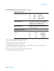
Internal DMM Measurement Characteristics (continued)
[1]
For 1 k unbalance in LO lead
[2]
For power line frequency ±0.08%
[3]
For power line frequency ±1% use 75 dB or ±2.5% use 60 dB
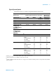
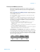
Frequency and period
Measurement method Reciprocal counting technique
Voltage ranges Same as AC voltage function
Gate time 1s, 100 ms, or 10 ms
Measurement time-out Selectable 3 Hz, 20 Hz, 200 Hz LF limit
Measurement Consideration All frequency counters are susceptible to error when
measuring low-voltage, low-frequency signals.
Shielding inputs from external noise pickup is critical
for minimizing measurement errors.
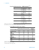
DC Current
Shunt resistance 5 for 10 mA, 100 mA; 0.1 for 1 A
Input protection 1A 250 V fuse on 34921A module
True RMS AC current
Measurement method Direct coupled to the fuse and shunt. AC coupled True
RMS measurement (measures the ac component
only).
Shunt resistance 5 for 10 mA; 0.1 for 100 mA, 1 A
Input protection 1A 250 V fuse on 34921A module
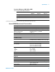
Thermocouple
Conversion ITS-90 software compensation
Reference junction type Internal, fixed, or external
Open thermocouple check Selectable per channel. Open > 5 k
Thermistor 44004, 44007, 44006 series
RTD = 0.00385 (DIN) and = 0.00392
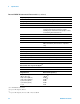
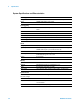
Measurement noise rejection 60 (50) Hz
[1]
DC CMRR 140 dB
AC CMRR 70 dB
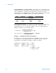
Integration time
Normal mode rejection
[2]
200 plc/3.33 s (4 s)
100 plc/1.67 s (2 s)
20 plc/333 ms (400 ms)
10 plc/167 ms (200 ms)
2 plc/33.3 ms (40 ms)
1 plc/16.7 ms (20 ms)
< 1 plc
105 dB
[3]
100 dB
[3]
95 dB
[3]
90 dB
[3]
85 dB
60 dB
0 dB