Agilent 34980A Multifunction Switch/Measure Unit Data Sheet Challenge the Boundaries of Test Agilent Modular Products
High-performance switch/measure unit provides a low-cost, highly flexible measurement platform If you use automated test equipment for design validation or manufacturing, you now have a cost-effective solution for many test system applications. The 34980A multifunction switch/measure unit provides functionality that is easy to set up and use, with a fast startup time. The 34980A helps you lower your cost of test and accelerate your test-system integration and development.
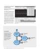
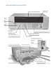
Easier signal routing with four 2-wire internal analog buses. You can route your measurements directly to the internal DMM, or you can connect to external instruments through the analog bus connector on the rear of the mainframe. And since you have four 2-wire buses, you can dedicate one bus for use with the internal DMM and use the other three buses for module extensions or additional signal routing between modules, reducing your wiring needs.
Standard interfaces take the hassle out of connecting to your PC Standard Ethernet, USB and GPIB interfaces are included in every mainframe. Use one of the built-in interfaces that is already available in your computer, or if you prefer, GPIB is still available. • USB offers the quickest and easiest connection scheme—it’s perfect for small systems and bench connections. • Ethernet offers high-speed connections that allow for remote access and control.
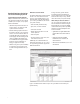
Free BenchLink Data Logger Software to Simplify data logging The BenchLink Data Logger software for the 34980A provides a convenient way to collect and analyze your data. This is a Windows® -based application that uses a familiar spreadsheet environment to define measurement data to be collected. The tab-based format makes it easy to set up and initiate scans. Simply identify the measurements you want to acquire, initiate the process and see the data displayed real-time.
Power and flexibility to get your job done Intuitive front panel with self-guiding menus See results on bright, multiline display Store and recall instrument setups Set I/O, date and other system features 6 1 ⁄ 2 digit DMM measurements with 11 functions Use keypad to enter channel number or knob to scroll Configure measurements, manage sequences, view errors and alarms Scan multiple channels, close specified channel list, or monitor results on a single channel Set up scan lists Store up to 500,000 read
Mix and match 34980A modules to create your own custom configuration The 34980A mainframe holds up to eight plug-in modules. Mix and match them to create a custom system to meet your switching and system control needs. You can easily add or replace modules as your needs change. Table 1.
34980A multiplexer switch modules H The 34980A multiplexer modules can be used to connect one of many different points to a single point. You can connect to an external instrument, or scan multiple analog signals to the internal DMM.
Multiple multiplexers can connect to the built-in analog buses, allowing you to scan up to 560 2-wire channels or 640 1-wire channels in a single mainframe. The 34921A also offers 4 channels for directly measuring current. Or if you need more current channels, shunts can be added to the terminal block for easy current measurements. The multiplexer modules feature breakbefore-make connections to ensure that no two signals are connected to each other during a scan.
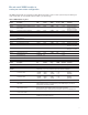
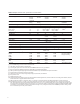
Table 3. Multiplexer selection table—specifications and characteristics 34921A 34922A 34923A 34924A 34925A Channels/configurations 40 2-wire 20 4-wire 4-current 1.
Table 3. Multiplexer selection table—specifications and characteristics—continued 34921A 34922A 34923A 34924A 34925A 100 M 100 M 1000 M 1000 M 10 V, 100 ma 10 M 10 M 10 M 10 M Rated load 100 k 100 k 10 k 10 k Unlimited within FET banks Unlimited within FET banks Unlimited within FET banks General characteristics Relay life, typical No load Scanning speeds [7] 100 ch/sec 100 ch/sec 500 ch/sec 500 ch/sec 1000 ch/sec Open/ close time, typical 4 ms/4 ms 4 ms/4 ms 0.5 ms/0.5 ms 0.
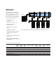
34980A matrix switch modules The 34980A matrix modules are full crosspoint matrices that allow you to connect any row to any column. This is a convenient way to connect multiple test instruments to multiple points on a device under test. Choose from the following features: H L H L H L H L H L H L H L ABus1 DMM (MEAS) 921 H L H L ABus2 DMM (SENS) 922 H L H L ABus3 923 • Latching armature relays—300 V, 1 A H L H L • High-speed reed relays—150 V, 0.
Table 4. Matrix selection table—specifications and characteristics 34931A 34932A 34933A 34934A Channels/configurations dual 4x8 8x8 4x16 dual 4x16 8x16 4x32 dual 4x8 8x8 4x16 quad 4x8, 1-wire quad 4x32 4x128 8x64 16x32 Switch type Armature latching Armature latching Reed non-latching Reed non-latching Input characteristics (per channel) [1] Max current (DC, AC RMS) Switch current Carry current 1A 2A 1A 2A 0.5 A /0.05 A [5] [8] 1.5 A /0.05 A 60 W 60 W 10 W 108 108 108 < 1.5 Ω < 1.
34980A general-purpose switch modules The 34980A general-purpose switches can be used to route signals or to control other system devices. These switches are ideal for device actuation and switching loads or power supplies.
34980A RF and microwave switch modules The 34980A offers a variety of RF and microwave switch modules—RF multiplexers, SPDT switching from DC to 26.5 GHz, or a switch/ attenuator driver module that allows you to control switches or attenuators external to the 34980A mainframe. 34941A/42A—from DC to 3 GHz The RF switch modules can be used to switch signals from DC to 3 GHz and above.
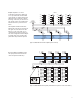
34942A typical initial crosstalk 0 dB -10 dB -20 dB -30 dB -40 dB -50 dB -60 dB -70 dB -80 dB -90 dB -100 dB 50 101 COM 50 102 50 201 COM 34946A Dual 1x2 SPOT Terminated Microwave Switch Figure 11. 34946A dual 1x2 SPDT terminated microwave switch 10 MHz 40 MHz 100 MHz 400 MHz 1 GHz 2 GHz Frequency 34942A typical initial insertion loss 0.0 dB 0.3 dB 0.6 dB 0.9 dB 1.2 dB 1.5 dB 1.8 dB 2.1 dB 2.4 dB 2.7 dB 3.0 dB 10 MHz 40 MHz 100 MHz 400 MHz 1 GHz 2 GHz Frequency 34942A typical initial VSWR 2.
Table 6. RF and microwave selection table—specifications and characteristics DC to 3 GHz DC to 26.5 GHz [3] 34941A 34942A 34946A 34947A Channels quad 1x4 quad 1x4 2 SPDT 3 SPDT Switch type 50 Ω unterminated, latching relays 75 Ω unterminated, latching relays 50 Ω terminated 50 Ω unterminated DC to 3 GHz DC to 1.5 GHz DC to 4 GHz, 20 GHz or 26.5 GHz DC to 4 GHz, 20 GHz or 26.5 GHz DC to 4 GHz < 0.42 dB, @ 20GHz < 0.69 dB, @ 26.5GHz < 0.8 dB DC to 4 GHz < 0.42 dB, @ 20 GHz < 0.
34945A/34945EXT microwave switch/attenuator driver This module allows you to control switches attenuators, and other devices external to the 34980A. The 34945A/ 34945EXT provides the power and control signals for many of the most popular microwave switches and attenuators. One 34945A/34945EXT combination can drive up to 64 switch coils—that’s 32 standard SPDT switches. The 34945A/EXT can be extended by adding additional 34945EXT boards. The first 34945EXT is powered by the mainframe.
34980A system control modules 34950A 64-bit digital I/O with memory and counter This module can be used to simulate or detect digital patterns. It has eight 8-bit digital I/O channels with handshaking, pattern memory, two 10 MHz counters with gate functions, and a programmable clock output. Digital input/output The digital I/O bits are organized into two banks of 32-bits. The I/O bits can be configured and programmed as inputs or outputs in 8-bit channels.
34951A 4-channel isolated D/A converter with waveform memory This module has four independent, isolated channels that output DC voltage up to ± 16 V or DC current up to ± 20 mA. The gain and offset can be adjusted on-the-fly. Each channel can be controlled manually, or use the onboard memory to download a waveform. The 500k of memory is global and can store up to 32 waveforms.
34952A multifunction module with 32-bit DIO, 2-channel D/A and totalizer Digital input/output characteristics Vin(L) < 0.8 V (TTL) The multifunction module offers the flexibility you need for system control. The 34952A has four 8-bit digital I/O channels, a 100kHz gated totalizer, and two ± 12 V analog outputs—all on a single earth-referenced module. The digital inputs and totalizer input may be included in a scan list.
34959A breadboard module Use this module to create your own custom designs inside the 34980A mainframe. You can control your custom circuits with access to both the +12 V and +5 V supplies, 28 relay drive lines and two 8-bit GPIO ports. Your design can be isolated from the analog buses or connected by loading the backplane switches. Simply mount your custom PC board or other components into the space provided and connect via the two ribbon connectors provided.
34980A system specifications and characteristics DMM accuracy ± (% of reading + % of range) Includes measurement error, switching error, and transducer conversion error Measurement including switch error [4] Function Range DC voltage (with 34921A/22A/ [10] [11] 31A/32A) Input impedance = Hi-Z 10 V range and below 100.0000 mV 1.000000 V 10.00000 V 100.0000 V 300.0000 V True RMS AC [5] voltage All ranges from 100.0000 mV to 100.0000 V 300.0000 V Frequency, etc.
Additional Low Frequency Error for ACV, ACI (% of reading) Frequency AC Filter Slow AC Filter Medium Additional Error for Frequency, Period (% of reading) Aperture (Digits) AC Filter Fast 10 Hz- 20 Hz 20 Hz - 40 Hz 40 Hz - 100 Hz 0 0 0 0.74 0.22 0.06 – – 0.73 100 Hz - 200 Hz 200 Hz - 1 kHz > 1 kHz 0 0 0 0.01 0 0 0.22 0.18 0 Frequency 1 second (6 1/2 digits) 0.1 seconds (5 1/2 digits) 0.01 seconds (4 /2 digits) 0 0 0 0 0 0 0 0.12 0.17 0.2 0.06 0.03 0.01 0 0.12 0.17 0.2 0.21 0.21 0.07 0.
34934A Multi-channel close speeds over GPIB (msec) Isolate or fixed mode Auto 100 mode Auto 0 mode Close 2 channels 0.97 1.22 1.31 Close 5 channels 0.43 0.54 0.56 Close 10 channels 0.22 0.28 0.29 Close 60 channels 0.13 0.17 0.21 Single channel measurement rates–DMM reading rates [1] [2] Function Resolution Rds/s DCV 4 1/2 digits (0.02 plc) 5 1/2 digits (1 plc) 6 1/2 digits (10 plc) 3000 59 6 2-wire resistance 4 1/2 digits (0.
Measurement characteristics with optional internal DMM DC voltage Measurement method A-D linearity Continuously integrating multi-slope III A-D converter 0.0002% of reading + 0.
Measurement characteristics with optional internal DMM continued DC operating characteristics Scanning inputs [4] [5] Function [7] DCV , DCI, and Resistance (≤10 kΩ) System specifications Digits 6 1/2 6 1/2 5 1/2 5 1/2 4 1/2 4 1/2 Readings/s 0.6 (0.5) 6 (5) 60 (50) 300 600 3000 Additional RMS noise error 0% of range 0% of range 0.001% of range [6] 0.001% of range [6] 0.01% of range [6] 0.
General specifications Power supply Agilent BenchLink data logger features Universal 100 V to 240 V ± 10% Power line frequency 50 – 60 Hz ± 10% automatically sensed Power consumption 150 VA Operating environment Full accuracy for 0 °C to 55 °C Full accuracy to 80% R.H. at 40 °C IEC 60664-1 pollution degree 1 Storage environment -40°C to 70°C Mainframe dimensions 133 H x 426 W x 341 D mm (5.25” x 16.8” x 14”) Full rack, 3 units high Configuration Spreadsheet-like channel configurations page.
Ordering instructions Mainframe – holds up to 8 plug-in modules 34980A Multifunction switch/measure mainframe Comes standard with “DMM” option, BenchLink Data Logger Software, User Guide on CD-ROM, Power cord and quickstart package. 34832A BenchLink Data Logger Pro Software Optional software package that adds limit checking and decision making for more complex applications.
Ordering instructions continued RF and microwave modules 34941A Quad 1x4 50-ohm 3-GHz RF multiplexer 20 – SMA Requires standard 50 ohm SMA RF cables, and optional 8710-2576 SMA Extender wrench for connecting SMA connectors 34942A Quad 1x4 75-ohm 1.
Cables [1] used for direct cable connection to module. some modules require 2 cables Y1135A 1.5 m 50-pin Dsub, M/F twisted pair with outer shield cable – 300 V Y1136A 3 m 50-pin Dsub, M/F twisted pair with outer shield cable – 300 V Y1137A 1.
T h e Mo d u l ar Tang r am The four-sided geometric symbol that appears in this document is called a tangram. The goal of this seven-piece puzzle is to create identifiable shapes—from simple to complex. As with a tangram, the possibilities may seem infinite as you begin to create a new test system. With a set of clearly defined elements—hardware, software—Agilent can help you create the system you need, from simple to complex. Challenge the Boundaries of Test Agilent Modular Products 3-Year Warranty www.