Agilent 34952A Multifunction Module User’s Guide Agilent Technologies, Inc.
Notices © Agilent Technologies, Inc. 2008 Warranty No part of this manual may be reproduced in any form or by any means (including electronic storage and retrieval or translation into a foreign language) without prior agreement and written consent from Agilent Technologies, Inc. as governed by United States and international copyright laws. Microsoft® and Windows® are U.S. registered trademarks of Microsoft Corporation.
Additional Safety Notices The following general safety precautions must be observed during all phases of operation of this instrument. Failure to comply with these precautions or with specific warnings or instructions elsewhere in this manual violates safety standards of design, manufacture, and intended use of the instrument. Agilent Technologies assumes no liability of the customer’s failure to comply with the requirements. General Do not use this products in any manner not specified by the manufacturer.
The Declaration of Conformity (DoC) for the 34980A mainframe instrument can be found on page iii in the 34980A Mainframe User’s Guide. That DoC applies to the 34980A mainframe and all available plug- in modules.
Contents 34952A Multifunction Module . . . . . . . . . . . . . . . . . . . . . . . . . . . . . . . . . . . . . . . . . . . . . . . . . .1 Digital Input/Output . . . . . . . . . . . . . . . . . . . . . . . . . . . . . . . . . . . . . . . . . . . . . . . . . . . . . . .1 Totalizer Input . . . . . . . . . . . . . . . . . . . . . . . . . . . . . . . . . . . . . . . . . . . . . . . . . . . . . . . . . . . .1 Analog Output (DAC) . . . . . . . . . . . . . . . . . . . . . . . . . . . . . . . . . . . . . . . . . . .
vi Agilent 34952A Multifunction Module User’s Guide
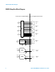
34952A Multifunction Module 34952A Multifunction Module The 34952A Multifunction Module with DIO, D/A, and Totalizer combines four 8- bit ports of digital input/output, a 100 kHz totalizer, and two ±12 volt earth- referenced analog outputs. You can include digital inputs and totalizer input in a scan list. You can make connections via standard 50- pin D- sub cables or the optional 34952T terminal block.
34952A SCPI Programming Examples 34952A SCPI Programming Examples The programming examples below provide you with SCPI command examples to use for actions specific to the general purpose switch modules. The slot and channel addressing scheme used in these examples follow the form sccc where s is the mainframe slot number (1 through 8) and ccc is the channel number. For information on specific configurations, refer to the simplified schematic on page 4.
34952A SCPI Programming Examples Example: Configuring the totalizer for count This command configures the totalizer to count on the rising edge (positive) or falling edge (negative) of the input signal. The following command configures the totalizer (channel 5) on a Multifunction module in slot 3 to count on the negative edge (falling) of the input signal.
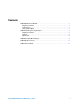
34952A Simplified Block Diagram 34952A Simplified Block Diagram Internal to the 34952A Module User-Supplied Connections Bit 0 8 Channel 001 Bit 7 Bit 8 8 Channel 002 DIO Bit 15 Bit 16 8 Channel 003 Bit 23 Bit 24 8 Channel 004 Bit 31 Count + 32 Bits Count - Totalizer Gate Channel 005 Gate 16 Bits D/A1 DAC 1H DAC 1L Channel 006 16 Bits D/A2 DAC 2H DAC 2L 4 Channel 007 Agilent 34952A Multifunction Module User’s Guide
34952A D-Sub Connector 34952A D-Sub Connector BIT 11 BIT 10 BIT 9 BIT 8 GND BIT 7 BIT 6 BIT 5 BIT 4 BIT 3 BIT 2 GND BIT 1 BIT 0 GND 17 16 15 14 13 12 11 10 9 8 7 6 5 4 3 BIT 22 BIT 21 BIT 20 33 32 31 BIT 31 BIT 30 BIT 29 50 49 48 Description Bit 0 Bit 1 Bit 2 Bit 3 Channel 1 Bit 4 Bit 5 Bit 6 Bit 7 Bit 8 Bit 9 Bit 10 Bit 11 Channel 2 Bit 12 Bit 13 Bit 14 Bit 15 Socket 4 5 7 8 9 10 11 12 14 15 16 17 21 22 23 25 GND BIT 19 BIT 18 BIT 17 BIT 16 BIT 15 30 2
34952T Terminal Block 34952T Terminal Block Each terminal block is labeled with the model number and the abbreviated module name. In addition, space is available on the label for you to write the slot number. The 34980A Product Reference CD (shipped with the instrument) contains a 34952T Wiring Log for you to document your wiring configuration for this module. You can open the wiring log file in Microsoft® Excel® or Adobe® Acrobat® format.
Index Index A analog output, 1 C connector pinouts, 5 D DAC output, 1 digital I/O, 1 D-sub pinouts, 5 M module description, 1 P pinouts, 5 programming examples, 2 S simplified block diagram, 4 T terminal block, 6 totalizer input, 1 W warranty, ii wiring log, 6 Agilent 34952A Multifunction Module User’s Guide 7
Index 8 Agilent 34952A Multifunction Module User’s Guide