Agilent 35670A Dynamic Signal Analyzer Supplement to Installation, Service and Operator’s Guide Agilent Technologies
Notices © Agilent Technologies, Inc. 2002, 2003, 2006 Warranty No part of this manual may be reproduced in any form or by any means (including electronic storage and retrieval or translation into a foreign language) without prior agreement and written consent from Agilent Technologies, Inc. as governed by United States and international copyright laws. Microsoft® and Windows® are U.S. registered trademarks of Microsoft Corporation.
In This Supplement Purpose The purpose of this supplement is to describe changes to the display of the Agilent 35670A. These changes apply only to instruments with a serial number higher than MY42506200 made after December 2002. Most users of the Agilent 35670A will see few or no changes in the operation of the instrument. The changes apply to specific sections of the Agilent 35670A Operator’s Guide, the Agilent 35670A Installation and Verification Guide, and the Agilent 35670A Service Guide.
Agilent 35670A Supplement
Contents 1 Overview Summary of Changes 8 Display 8 Rear panel 8 Board revisions 8 2 Installation and Verification Guide Preparing the Analyzer for Use 10 To connect the analyzer to an external monitor 3 10 Operator’s Guide Formatting the Display 12 To control the screen 12 4 Service Guide Preparing the Analyzer for Use 14 AC Power Cable and Grounding Requirements To connect the analyzer to an external monitor Troubleshooting the Analyzer 16 To perform initial verification 16 To troubleshoot the powe
What to do before replacing the CPU assembly What to do after replacing an assembly 30 To remove CPU 31 To remove NVRAM 32 To remove memory 32 To remove motherboard 32 Replaceable Parts 33 Assemblies 33 Cables 34 Instrument Covers and Handles Front Panel Parts 35 Rear Panel Parts 36 Chassis Parts 36 Miscellaneous Parts 36 Circuit Descriptions 37 Overall Block Diagram A7 CPU 39 A8 Memory 43 A9 NVRAM 43 A102 DC-DC Converter 29 34 37 43 Voltages and Signals 44 Voltages and Signals 44 Assembly Locations an
Agilent 35670A Dynamic Signal Analyzer Supplement to Installation, Service and Operator’s Guide 1 Overview The changes to the Agilent 35670A Dynamic Signal Analyzer will not be noticeable to most users. The changes covered in the supplement include: • new display • new CPU board that also incorporates the memory and NVRAM boards • memory options are now standard • new external monitor interface which supports XGA resolution.
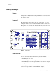
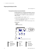
1 Overview Summary of Changes Display Changes in the display will be imperceptible to most users. The changes are mainly at the assembly level and are addressed in the Service Guide. Rear panel The illustration below shows the new rear panel. The only change is in the location of the external monitor connection. This is the only place in this supplement that shows the new rear panel unless a detailed illustration is required.
Agilent 35670A Dynamic Signal Analyzer Supplement to Installation, Service and Operator’s Guide 2 Installation and Verification Guide The Agilent 35670A has incorporated a standard VGA monitor output and is now compatible with most monitors.
2 Installation and Verification Guide Preparing the Analyzer for Use Page in original guide 2-13 To connect the analyzer to an external monitor The External Monitor is a standard 15- pin miniature connector that can interface with an external monitor. The monitor must be compatible with the 49.74 kHz line rate, 61.6 Hz frame rate, analog RGB signals, and TTL sync signals provided by the Agilent 35670A. 1 Set the analyzer’s power switch to on (|). 2 Set the monitor’s power switch to on.
Agilent 35670A Dynamic Signal Analyzer Supplement to Installation, Service and Operator’s Guide 3 Operator’s Guide Changes in this guide include display attributes (resolution, size, brightness) and external monitor connections.
3 Operator’s Guide Formatting the Display To control the screen Page in original guide 2-4 Disregard item 2. Display brightness is no longer adjustable.
Agilent 35670A Dynamic Signal Analyzer Supplement to Installation, Service and Operator’s Guide 4 Service Guide The CPU board has a new number (A17) and is a consolidation of the original CPU assembly (A7), memory assembly (A8) and the Non- Volatile RAM option board (A9). Memory options are now standard. There is a new higher resolution display, and a power inverter to replace the dc- dc converter. The external monitor port is now a standard VGA interface with XGA output resolution.
4 Service Guide Preparing the Analyzer for Use AC Power Cable and Grounding Requirements Page in original guide 2-4 New power cable illustration shows new number for United Kingdom Option 900 cable.
4 Service Guide To connect the analyzer to an external monitor Page in original guide 2-13 The External Monitor is a standard 15- pin miniature connector that can interface with an external monitor. The monitor must be compatible with the 49.74 kHz line rate, 61.6 Hz frame rate, analog RGB signals, and TTL sync signals provided by the Agilent 35670A. 1 Set the analyzer’s power switch to on (|). 2 Set the monitor’s power switch to on.
4 Service Guide Troubleshooting the Analyzer To perform initial verification Page in original guide 4-5 New illustrations for component locators show new test points and new connector locations: 16 Agilent 35670A Supplement
Service Guide 4 Pin-out common to all 36-pin connectors P17 P11 TP202 Figure 5 Agilent 35670A Supplement A17 CPU board test point locator 17
4 Service Guide Replace Step 7: Check signals required for power up. • Using a logic probe, check the following signals. Signal Name PVALID RSTn ASn +5V +3.
Service Guide 4 To troubleshoot the power supply Page in original guide 4-13 Step 5: Replace the bullet concerning reconnecting assemblies: • Reconnect one assembly at a time in the following order: 1 A17 CPU (A17 P10 to A99 J7) 2 A102 Power Inverter (cable to A17 P13) 3 A11 Keyboard Controller (Cable to A17 P1) 4 A100 Disk Drive (cable to A17 P3) The illustration for component locator shows new connector locations.
4 Service Guide To troubleshoot power-up failures Page in original guide 4-15 Replace the first five rows of the table: Failing Power-up Message LEDs MC68030 Processor MC68882 Coprocessor Bootrom Display Main RAM ProgramROM DSP Fast bus MFP 20 Probable Faulty Assembly or Next Test A17 CPU A17 CPU A17 CPU A17 CPU A17 CPU Agilent 35670A Supplement
Service Guide 4 To troubleshoot CPU, memory and buses failures Page in original guide 4-19 Step 1: Disregard references to Memory Assembly and incorporate the related information into A17 CPU.
4 Service Guide To troubleshoot display failures Page in original guide 4-23 Replace entire section Use this test to isolate display failures to the A101 Display assembly, A102 assembly, or the A17 CPU assembly ✔ Step 1. Check the power inverter assembly. • Set the power switch to off (O). • Remove the cable connected to P13 on the A17 assembly. • Set the power switch to on (|) • Measure voltage at P13 pin 1 on A17 assembly. • If voltage is not +5Vdc the A17 board may be faulty.
Service Guide 4 Pin-out for P13 connector Pin-Out for P14 Figure 8 A17 CPU board connector locator, circuit side ✔ Step 3. Determine the probable faulty assembly by comparing the analyzer’s symptoms to the following table.
4 Service Guide To troubleshoot IIC bus failures Page in original guide 4-26,27 A new illustration above step 2 shows new connector pin- outs: A1 2 34 A50 B50 C50 B1 C1 Figure 9 A17 CPU motherboard (P10) connector pin locations ✔ Step 2. Check the serial clock (SCL). • Attach a logic probe to A17 P1- 15 (SCL) or P10 pin B10. • Set the power switch to on (|). • Press S5 (reset switch) while monitoring A17 P10 pin B10 (SCL), the power- on LEDs, and the display.
Service Guide 4 • If no error messages are displayed after Booting System or A17 DS101 (green run LED) is off, go to page 4- 29, “To troubleshoot fast bus failures.” DS 5 4 3 2 6 MSB A17 CPU 7 8 9 10 1 Green Yellow S5 Figure 10 Power-on LEDs and reset switch ✔ Step 3. Check the serial data line (SDA). • Attach the logic probe to A17 P10 pin C11 (SDA). • Press S5 while monitoring A17 P10 pin C11 (SDA), the power on LEDs and the display.
4 Service Guide To troubleshoot fast bus failures Page in original guide 4-30 New table: A17 P10 Pin B14, C14, B15, C15, B16 B22 B24 C12 C19 C23 C24 Signal Name FA1 to FA5 ECLK FSELAn BRESETn FRW FIFOENn FSELSn TTL Logic State in Test Mode Toggling Toggling Toggling Low Toggling High Toggling New illustration showing location of motherboard connector pins.
Service Guide 4 To troubleshoot memory or battery failures Page in original guide 4-67,68 Replace the last five bulleted items: • If the date is 01- 01- 01, the battery- backed- up memory is functioning correctly. Enter the current date. Go to page 4- 13, “To perform self tests,” to continue troubleshooting. • Set power switch to off (O) • Check that the voltage at TP200 is 2.6Vdc to 3.1Vdc. • If the voltage is correct, the memory is probably faulty.
4 Service Guide Adjusting the Analyzer Adjusting the analyzer Page in original guide 5-2 Delete the first row of the table referring to frequency reference. The frequency is no longer adjustable. To adjust the frequency reference Page in original guide 5-5 Disregard this section. The frequency reference is not adjustable. To adjust the display voltage Page in original guide 5-21,22 Disregard this section. The display voltage is not adjustable.
Service Guide 4 Replacing Assemblies What to do before replacing the CPU assembly Page in original guide 6-3 The EEPROM is now U111 on the A17 CPU assembly.
4 Service Guide What to do after replacing an assembly Page in original guide 6-5 The rows referring to A7 CPU, A8 Memory, and A9 NVRAM are replaced with: Assembly Replaced A17 CPU Required Adjustment No Required Performance Test No Note that the frequency adjustment is no longer needed. Disregard the last two rows of the table referring to adjustments of the Display and the DC- DC Converter (now a Power Inverter). There are no adjustments for these items.
Service Guide 4 To remove CPU Page in original guide 6-11 New illustration in step 3 showing an additional cable: Figure 14 Disconnect the cables from A17 Agilent 35670A Supplement 31
4 Service Guide To remove NVRAM Page in original guide 6-12 Disregard this section. The NVRAM is now on the CPU board. To remove memory Page in original guide 6-13 Disregard this section. The memory in now on the CPU board. To remove motherboard Page in original guide 6-17 Disregard step 5.
Service Guide 4 Replaceable Parts Assemblies Page in original guide 7-4 A17 Power Inverter Bezel Assembly Figure 15 Assemblies Reference designator A17 replaces A7, A8 and A9. There is also a replacement motherboard, bezel assembly, display assembly and DC- DC converter assembly.
4 Service Guide Cables Page in original guide 7-6 Disregard Memory and NVRAM sections of block diagram.
Service Guide 4 Front Panel Parts Page in original guide 7-9 MP211 Figure 16 Front panel parts Three parts have been replaced and a new one added: Ref Des MP201 MP210 MP212 MP211 Agilent 35670A Supplement Agilent Part Number 35670-22021 35670-29321 35670-44723 8160-1502 Description CSTG-FRT FRAME MACH&PAINTED LNZ-FLTR RFI/OPTICAL DISPLAY GASKET 4 RFI ELASTOMER STRIPS 35
4 Service Guide Rear Panel Parts Page in original guide 7-10 One part has been replaced: Ref Des Agilent Part Number MP300 35670-00221 Description SHTF REAR PANEL W/SILKSCREEN Chassis Parts Page in original guide 7-11 Two parts have been replaced: Ref Des Agilent Part Number MP400 35670-00122 MP401 35670-00123 Description SHTF-CHASSIS ASSY SHTF WALL ASSY FRONT Miscellaneous Parts Page in original guide 7-12 One part has been replaced and a new part has been added: Ref Des Qty A17BT1 1 2 36 Agilen
Service Guide 4 Circuit Descriptions Overall Block Diagram Page in original guide 8-4,5 The Memory and NVRAM assemblies are now incorporated into the CPU assembly. The additional NVRAM option assembly is now standard and consolidated onto the CPU assembly. The DC- DC Converter has been replaced with a Power Inverter which generates the display backlight voltage.
4 Service Guide Figure 18 Four channel overall block diagram 38 Agilent 35670A Supplement
Service Guide 4 A7 CPU Page in original guide 8-26 through 29 This is now the A17 CPU. Delete all references to A8 memory and A9 NVRAM as separate assemblies since they are now incorporated on the CPU board. The A17 board now includes Non- Volatile Memory Storage operations among its tasks. The Math Co- processor is 20 MHz rather than 40 MHz (error in previous documentation). The 40 MHz oscillator is now a precision clock oscillator and is no longer adjustable.
I/O DEVICES S5 Reset Logic and Voltage Supervisor 68030 Battery Backed SRAM A B AND Battery backed SRAM 3 (PD0-31) (PA2-23) Memory Controller Firmware ROM DRAM 3.
Service Guide 4 Real Time Clock Frame Buffer1 Frame Buffer2 Display Controller Video Gate Array Video DAC Buffer TTL RGB Data Bus HSYNC VSYNC R G B VSYNC HSYNC LVD Data External Display Connector LCD Serializer Inverter control Inverter CCFL backlights Figure 20 CPU Block Diagram: Interface Agilent 35670A Supplement 41
4 Service Guide +5V RUN (GREEN) RESET RSTn RESET RESETn Buffer +5V RESETINn test point To Disk I/F TO IIC Controller To A11 Keyboard Controller To Disk I/F To Display I/F To HP-IB Interface To MFP To MC56001 To DMA Controller To A6 Digital To A5 Analog P8(S) Reset +5V S5 RSTn PVALID DCOM (from power supply) Reset Generator MPU HALTn To battery-backed SRAM control circuit Figure 21 Reset logic Reset logic all references to S2 are changed to S5 and there is a new block diagram.
Service Guide 4 A8 Memory Page in original guide 8-30,31 The memory has been incorporated into the CPU board. Therefore, the information in the sections on Memory Controller and FLASH ROM, DRAM, and SRAM is now added to the section on the A17 CPU. Disregard the rest of this section A9 NVRAM Page in original guide 8-32 The NVRAM has been incorporated into the CPU board. Disregard this section.
4 Service Guide Voltages and Signals Voltages and Signals Page in original guide 9-2 The references in the table to A8 Memory and A9 NVRAM are deleted since the circuits are now consolidated onto the A17 CPU board.
Service Guide 4 Assembly Locations and Connections Page in original guide 9-3,4,5 Bezel Assembly Power Inverter A17 Figure 22 Assembly locations Agilent 35670A Supplement 45
4 Service Guide LCD A17 CPU and memory Power Inverter Backlights CCFL Figure 23 Assembly connections for two-channel analyzer 46 Agilent 35670A Supplement
Service Guide 4 LCD A17 CPU and memory Power Inverter Backlights CCFL Figure 24 Assembly connections for four-channel analyzer Agilent 35670A Supplement 47
4 Service Guide Power Supply Voltage Distribution Page in original guide 9-6 In the table the references to paths to the A8 and A9 boards is deleted since the circuits are now on the A17 CPU board.
Service Guide 4 A9 NVRAM Page in original guide 9-12, 13 The NVRAM is in now incorporated into the A17 CPU board and the following information should be transferred to the A17 signal descriptions: PROTCTn VBATT Protect–A low on this line disables the battery-backed static RAM. This line is low during power-up and power-down, when the CPU assembly’s microprocessor is externally reset, and when +5 volts is too low.
4 Service Guide A101 Display Page in original guide 9-36 The following table lists signals routed between the A17 board and the LCD display assembly. All signals are generated on the A17 board and are used by the display assembly. A description of each signal follows the table. All data lines are LVDS. CLK + CLK – Pixel Data Pixel Data Pixel Data Pixel Data Pixel Data Pixel Data VCC Gnd 2 2 1 1 0 0 + – + – + – 6 7 9 10 12 13 15 16 19,20 1,2,3,4,5,8,11,14,17,18 CLK: LVDS pair carrying the 66.
Service Guide 4 A102 DC-DC Converter Page in original guide 9-37 This assembly is now a Power Inverter. The following table lists signals routed between the A17 board and the A102 Power Inverter. A description of each signal follows the table: VCC Gnd BLight_ON 1,2 3,4,7,8 5 VCC: 5 Volts BLight_ON: Generated by U135 to turn on and off the display backlights for power saver mode.
4 52 Service Guide Agilent 35670A Supplement