Agilent 16451B DIELECTRIC MATERIAL TEST FIXTURE Operation Manual Manual Change Agilent Part No. N/A June 2008 Change 1 Following note is added on the following designated locations. NOTE Be careful not to contaminate or not to make a scratch on the surface of the electrode. A scratch or contamination of the electrode’s surface sometimes prevents the measured capacitance from falling within the limits shown in “Electrode Adjustment” (Page 3-36).
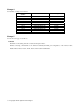
Change 4 Correct Table 1-3 (Page1-5) as follows. Instrument Model Number 4192A 4194A 4263B 4268A 4278A 4279A 4284A 4285A 4288A 4294A E4980A Correction Function 1m Cable Compensation OPEN/SHORT OPEN/SHORT OPEN/SHORT/LOAD OPEN/SHORT/LOAD OPEN/SHORT/LOAD OPEN/SHORT/LOAD OPEN/SHORT/LOAD OPEN/SHORT/LOAD OPEN/SHORT/LOAD OPEN/SHORT/LOAD OPEN/SHORT/LOAD available available available available available available available available available available available Change 5 Correct the text in page 2-3 as follows.
Change 6 Replace the contents of page 2-4 by the following, Dissipation Factor Accuracy (Δ tan δ) [m] The surfaces of material are assumed to be ideally parallel, flat and smooth. The above equation is only compatible for electrodes A and B.
Change 7 Correct the sentence at “16451B Overview” in page 3-1. The 16451B is a test fixture for measuring disc and lm dielectric materials when connected to Agilent’s LCR meters or impedance analyzers, and is usable up to 30 MHz. Change 8 Correct the sentence of step 8.in Page 3-43. Keep pressing the Guarded/Guard electrode pressure adjuster shown in Figure 3-25 and turn the three screws in a clockwise sequence until the measured capacitance value is within the limits listed in Table 3-5.
Agilent 16451B DIELECTRIC MATERIAL TEST FIXTURE Operation Manual マニュアル チェンジ Agilent Part No. N/A June 2008 変更 1 下記脚注を以下に指定するページに追加してください。 記: 電極の表面は汚したりキズをつけることのないよう取り扱いには十分注意してください。電極表面上の汚れやキズ によって容量を測定する際、“電極の調節” (Page 3-33) で提示されるリミットの範囲に収まらない可能性が発生し ます。 このような状況が発生した場合には電極を交換するかお近くのアジレントテクノロジーの営業、もしくはサービスまで お問い合わせください。 容量を測定した際、その測定結果がリミットに収まっている場合には、電極を交換する必要はありません。 追加箇所: 1. Page 3-26 2. Page 3-33 電極の平行度の粗調節の項の前 3. Page 3-37 電極水平置きの微調節の項の前 4. Page 3-39 5.
変更 3 1-4 ページの表 1-2 の脚注を下記に変更してください。 *1: 16451B を使用する際の 4194A の測定周波数の上限は、30 MHz となります。 *2: 16451B を使用する際の 4294A の測定周波数の上限は、30 MHz となります。 変更 4 1-5 ページの 表 1-3 を以下の表に差し替えてください。 Instrument Model Number 4192A 4194A 4263B 4268A 4278A 4279A 4284A 4285A 4288A 4294A E4980A Correction Function 1m Cable Compensation OPEN/SHORT OPEN/SHORT OPEN/SHORT/LOAD OPEN/SHORT/LOAD OPEN/SHORT/LOAD OPEN/SHORT/LOAD OPEN/SHORT/LOAD OPEN/SHORT/LOAD OPEN/SHORT/LOAD OPEN/SHORT/LOAD OPEN/SHORT/LOAD available available available avail
6-2: 2-4 ページ 測定確度の項に下記を追加してください。 電極 A と電極 B だけに対応する確度を表す。 被測定材料の両面が理想的に平行・平坦で滑らかであることを前提とする。 C Copyright 2008 Agilent Technologies ○
C Copyright 2008 Agilent Technologies ○
4294A の設定条件 1. 信号レベル: 500 mV 2. BW: 5 3. ケーブル長: 1m 4.
MANUAL CHANGES Agilent 16451B MANUAL IDENTIFICATION Model Number: 16451B Date Printed: Oct. 2000 Part Number: 16451-90020 DIELECTRIC TEST FIXTURE Operation and Service Manual This supplement contains information for correcting manual errors and for adapting the manual to newer instruments that contains improvements or modifications not documented in the existing manual. To use this supplement 1. Make all ERRATA corrections 2.
Page 4-5, Table 4-3.
Agilent 16451B DIELECTRIC TEST FIXTURE OPERATION AND SERVICE MANUAL SERIAL NUMBERS This manual applies directly to instruments with serial number pre x 2916J. For additional important information about serial numbers, read Chapter 2, \Serial Number" of this Operation and Service Manual. Agilent Part No.
Notice The information contained in this document is subject to change without notice. This document contains proprietary information which is protected by copyright. All rights are reserved. No part of this document may be photocopied, reproduced, or translated to another language without the prior written consent of the Agilent Technologies. Agilent Technologies Japan, Ltd.
Manual Printing History The manual printing date and part number indicate its current edition. The printing date changes when a new edition is printed. (Minor corrections and updates which are incorporated at reprint do not cause the date to change.) The manual part number changes when extensive technical changes are incorporated.
Safety Summary The following general safety precautions must be observed during all phases of operation, service, and repair of this xture. Failure to comply with these precautions or with speci c WARNINGS given elsewhere in this manual violates safety standards of design, manufacture, and intended use of the xture. The Agilent Technologies assumes no liability for the customer's failure to comply with these requirements.
How To Use This Manual Chapter 1 Installation Chapter 2 General Information This is the Operation Manual for the 16451B Dielectric Test Fixture, containing information on installation, con guration, operation, and service in the following four chapters and six appendices. After you receive your 16451B, begin with Chapter 1. The 16451B is designed to measure a dielectric using Agilent Technologies's LCR meters or impedance analyzers.
Typeface Conventions Bold Boldface type is used when a term is de ned. For example: icons are symbols. Italics Italic type is used for emphasis and for the titles of manuals and other publications. Italic type is also used for keyboard entries when a name or a variable must be typed in place of the words in italics. For example: copy lename means to type the word copy, to type a space, and then to type the name of a le such as file1.
Limitation Of Warranty The foregoing warranty shall not apply to defects resulting from improper or inadequate maintenance by the buyer, buyer-supplied software or interfacing, unauthorized modi cation or misuse, operation outside of the environmental speci cations for the product, or improper site preparation or maintenance. No other warranty is expressed or implied. Agilent Technologies speci cally disclaims the implied warranties of merchantability and tness for a particular purpose.
Contents 1. Installation Introduction . . . . . . . . . . . . Product Description . . . . . . . . Initial Inspection . . . . . . . . . . Compatible Measurement Instruments Error Correction . . . . . . . . . . . . . . . . . . . . . . . . . . . . . . . . . . . . . . . . . . . . . . . . . . . . . . 2. General Information Introduction . . . . . . . . . . . . . . . . . . . . . Safety Considerations . . . . . . . . . . . . . . . . . Serial Number . . . . . . . . . . . . . . . . . . . . Speci cations . .
3. Operation Introduction . . . . . . . . . . . . . . . . . . . . . 16451B Overview . . . . . . . . . . . . . . . . . . . Fixture Assembly . . . . . . . . . . . . . . . . . . Furnished Accessories . . . . . . . . . . . . . . . Dielectric Measurement Basic . . . . . . . . . . . . . Basic theory . . . . . . . . . . . . . . . . . . . . Guard Electrode . . . . . . . . . . . . . . . . . . Measurement Method . . . . . . . . . . . . . . . . . Contacting Electrode Method (used with Rigid Metal Electrode) . . . . .
Typical Measurement Procedure by the Measurement Methods . . . . . . . . . . . . . . . . . . . . Contacting Electrode Method . . . . . . . . . . . Procedure . . . . . . . . . . . . . . . . . . . Equations . . . . . . . . . . . . . . . . . . . Non-Contacting Electrode Method . . . . . . . . . Procedure . . . . . . . . . . . . . . . . . . . Equations . . . . . . . . . . . . . . . . . . . Check Electrode Parallelism . . . . . . . . . . . . . Measurement Examples . . . . . . . . . . . . . . . Using the 4194A .
D. Sample program Sample ASP Program for the 4194A . . . . . . . . . . Sample Program for the 4284A . . . . . . . . . . . . E.
Figures 1-1. 2-1. 2-2. 2-3. 2-4. 2-5. 2-6. 2-7. 2-8. 2-9. 3-1. 3-2. 3-3. 3-4. 3-5. 3-6. 3-7. 3-8. 3-9. 3-10. 3-11. 3-12. 3-13. 3-14. 3-15. 3-16. 3-17. 3-18. 3-19. 3-20. 3-21. 3-22. 3-23. 3-24. 3-25. 3-26. 3-27. 3-28. 3-29. Product Overview . . . . . . . . . . . . . . . . . Serial Number Plate . . . . . . . . . . . . . . . . Electrode A, MUT Thickness: 1mm . . . . . . . . . Electrode B, MUT Thickness: 1mm . . . . . . . . . Dimensions of Electrode-A . . . . . . . . . . . . . Dimensions of Electrode-B . . . .
3-30. 3-31. 3-32. 3-33. 3-34. 3-35. 4-1. 4-2. 4-3. 4-4. B-1. B-2. Contents-6 Contacting Electrode Method (Rigid Metal Electrode) . Contacting Electrode Method (Thin Film Electrode) . . Non-Contacting Electrode Method (Air Gap Method) . Sample Result of Cp-D Measurement Using the 4194A Sample Result of Dielectric Constant Using the 4194A Airgap E ects . . . . . . . . . . . . . . . . . . . Slide Stand Assembly . . . . . . . . . . . . . . . . Micrometer Stand Replacement . . . . . . . . . . .
Tables 1-1. Contents . . . . . . . . . . . . . . . . . . . . . . 1-2. Measurement Frequency Range of Compatible Instruments . . . . . . . . . . . . . . . . . . . 1-3. Correction Functions of the Compatible Instruments . 2-1. Available Test Material Dimensions . . . . . . . . . 3-1. Name of Fixture Assembly . . . . . . . . . . . . . 3-2. Name of Furnished Accessories . . . . . . . . . . . 3-3. Measured Capacitance Limits When the Micrometer is Set to 0.01 mm . . . . . . . . . . . . . . . . . 3-4.
1 Installation Introduction This chapter provides the information necessary for receiving and performing an incoming inspection, and preparing the 16451B for use. The WARNINGs, CAUTIONs, and NOTEs given throughout this document must be carefully followed to ensure the operator's safety and to not damage the 16451B. Product Description The 16451B is a Dielectric Test Fixture used with LCR meters and impedance analyzers for accurate measurement of insulating and dielectric materials.
Initial Inspection 1-2 Installation This xture has been carefully inspected electrically and mechanically before being shipped from the factory. It should be in perfect condition, no scratches, dents or the like, and it should be in perfect electrical condition. Verify this by carefully performing an incoming inspection to check the xture for signs of physical damage and missing contents. If any discrepancy is found, notify the carrier and Agilent Technologies.
Figure 1-1. Product Overview Table 1-1. Contents Description No.
Compatible Measurement Instruments This section speci es the compatible instruments used with the 16451B and their measurement frequency ranges and error correction functions. You should choose an instrument while considering measurement frequency range, capacitance measurement accuracy, error function, etc. Table 1-2 lists the measurement frequency ranges for these instruments when they are used with the 16451B. For more information, refer to the technical data sheet of each instrument. Table 1-2.
Table 1-3. Correction Functions of the Compatible Instruments Instrument Correction 1 m Cable Model Number Function Compensation 4192A OPEN/SHORT available 4194A OPEN/SHORT available 4263B OPEN/SHORT/LOAD available 4268A OPEN/SHORT/LOAD available 4278A OPEN/SHORT/LOAD*1 available 4279A OPEN/SHORT/LOAD available *1 4284A OPEN/SHORT/LOAD available 4285A OPEN/SHORT/LOAD available 4294A OPEN/SHORT/LOAD available *1 A working standard is required to perform the LOAD compensation.
2 General Information Introduction Note Safety Considerations This chapter describes safety consideration, serial number, speci cations, supplemental performance characteristics, and information on storing and repacking the 16451B. In this manual, the term dielectric constant means \relative dielectric constant". In common usage the word \relative" is frequently dropped. The term \dielectric constant" is often called \permittivity" in other documents. This manual will unify it to \dielectric constant".
Serial Number A serial number is stamped on the serial number plate, as shown in Figure 2-1, attached to the 16451B. The serial number used by Agilent Technologies consists of ten characters. The characters are separated into two sections. The rst four digits and a letter are the serial number pre x, and the last ve digits are the su x. The pre x is the same for all identical 16451B's; it changes only when a change is made to the 16451B.
Speci cations Function This section lists the complete 16451B speci cations. These speci cations are the performance standards and limits against which the 16451B is tested. When shipped from the factory, the 16451B meets the speci cations listed in this section. Test xture for measuring dielectric constant and dissipation factor. Permits connecting solid materials to the unknown terminals (4-terminal pair con guration) of the 4192A, 4194A, 4263B, 4268A, 4278A, 4279A, 4284A, 4285A and 4294A.
Supplemental Performance Characteristics Measurement Accuracy when using contact electrode method This section gives supplemental performance characteristics. Supplemental performance characteristics are not speci cations, but are typical characteristics included as additional information for the operator. Supplemental performance characteristics are not guaranteed. 1"0 "r 0Accuracy ( 0 rm ) "rm tan < 0.1 : 2 d 2 0 + 100("rm 0 1) [%] (typical) Az + 0:04f2"0rm "0 t ("0rm + 0:t01 ) tan < 0.
Permittivity Measurement Accuracy including 4294A (Supplemental Characteristics) Figure 2-2.
Figure 2-3. Electrode B, MUT Thickness: 1mm 1. 2. 3. 4.
Electrode Dimensions Guarded/Guard Electrode (4 types, changeable) 1. For materials without applied thin lm electrodes Figure 2-4. Dimensions of Electrode-A Figure 2-5.
2. For materials with applied thin lm electrodes Figure 2-6. Dimensions of Electrode-C Figure 2-7.
Unguarded Electrode Figure 2-8. Dimensions of Unguarded Electrode Available Test Material Dimensions Table 2-1.
Micrometer Resolution 10 m Dimensions of Fixture Assembly Figure 2-9.
Storage and Repacking Environmental Requirements Original Packaging Other Packaging This section describes the environment for storing or shipping the 16451B, and how to repackage the 16451B for shipment when necessary. The 16451B should be stored in a clean, dry environment. The following environmental limitations apply for both storage and shipment.
3 Operation Introduction Warning 16451B Overview Fixture Assembly This chapter describes the product overview, basic theory of measuring dielectric constant using the 16451B, methods for measuring dielectric constant step by step, details of measurement procedure basic measurement procedure summarized and typical measurement procedures with measurement results using the 4194A and 4284A. The last part of this chapter describes measurement error factors.
Figure 3-1. Fixture Assembly The name and description of the xture assembly shown in Figure 3-1 are listed in the following table (Table 3-1).
Table 3-1. Name of Fixture Assembly No. (1) Name of Part Unguarded electrode (2) Guarded/Guard electrode (3) Guarded/Guard electrode attachment screw Micrometer (4) (5) Adjustment knob (large knob) (6) Ratchet knob (small knob) Cable assembly (7) (8) (9) Unguarded electrode adjustment screws Guarded/Guard electrode pressure adjuster Caution Description This electrode is connected to the Hc(High current) and Hp(High potential) terminal of the instrument.
Furnished Accessories The 16451B provides some accessories, such as 4 types of changeable electrodes and their covers, an attachment for error correction, Hex key, and Carrying case. Figure 3-2 and Table 3-2 show the furnished accessories. Figure 3-2.
No. (1) (2) (3) (4) (5) (6) (7) Table 3-2. Name of Furnished Accessories Name of accessory Description Electrode-A (38 mm This electrode is used to measure a material without thin lm electrode and consists of a Guarded electrode ( 1 -a) and a Guarded/Guard Guard electrode ( 1 -b). The diameter of guarded electrode is electrode) 38 mm. The electrode is provided with a cover ( 1 -c) to protect its surface.
Dielectric Measurement Basic Basic theory This section contains information of the basic theory of dielectric measurements and its measurement methods. This section describes the basic theory of dielectric constant measurement. The dielectric constant, a fundamental parameter of insulating or dielectric materials, is calculated from the capacitance value when the material is used as the dielectric. A practical measurement procedure is described in \Typical Measurement Procedure by the Measurement Methods".
Area of electrode [m2 ] Thus, the relative dielectric constant (generally called the dielectric constant) of the test material, r , can be obtained by measuring the capacitance value and calculating using the following equation. A t 2 Cp A 2 o t 2 Cp = 2 d 2 2 2 o r = Where, Diameter of electrode [m] The dielectric dissipation factor (= tan ; loss tangent) of test material, Dr can be obtained directly by measuring the dissipation factor.
Guard Electrode The dielectric constant of the disk material shown in Figure 3-3 is calculated from the measured capacitance value, as above-mentioned. When the capacitance of the disk material is measured, there is measurement error caused by stray capacitance at the edge of the test material, as shown in the left of gure of Figure 3-4.
Measurement Method This section describes three applicable measurement methods for the 16451B. As the previous section \Dielectric Measurement Basic" explains, capacitance measurement of the test material is required when the dielectric constant of a solid test material is to be obtained. There are many kinds of methods to measure the capacitance of a solid material.
Figure 3-6.
Contacting Electrode Method (used with Rigid Metal Electrode) This method uses Rigid electrodes which make contact directly the surface of the test material. This method is applicable for thick, smooth or slightly compressible materials.
Dielectric constant and dissipation factor of a test material can be obtained using the following equations. Parameters Needed: Cp Equivalent parallel capacitance [F] D Dissipation factor ta Average thickness of test material [m] A Area of Guarded electrode [m2] d Diameter of Guarded electrode [m] (38210-3 [m] or 5210-3 [m]) o =8.
Electrodes of the 16451B The 16451B provides two applicable electrodes, Electrode-A (38 mm electrode) and Electrode-B (5 mm electrode), for the Contacting Electrode method (Rigid Electrode method) to match the size of test material as shown in Figure 3-8. When these electrodes are used, the diameter of test materials should be much greater than the inner diameter of the Guard electrode and smaller than or equal to 56 mm.
Applicable Size of Test Material for Electrode-A (38 mm Guarded/Guard Electrode) Diameter of material Thickness of material greater than or equal to 40 mm and smaller than or equal to 56 mm less than or equal to 10 mm Figure 3-9.
Applicable Size of Test Material for Electrode-B (5 mm Guarded/Guard Electrode) Diameter of test material Thickness of test material greater than or equal to 10 mm and smaller than or equal to 56 mm less than or equal to 10 mm Figure 3-10.
Contacting Electrode Method (used with Thin Film Electrode) This method uses thin lm electrodes applied on the test material. The thin lm electrodes contact with the 16451B's electrodes. This method is applicable for materials on which the thin lm electrodes can be applied without changing its characteristics. It should be noted that it is di cult to remove the thin lm electrodes after the measurement.
Dielectric constant and dissipation factor of a test material can be obtained using the following equations. Parameters Needed: Cp Equivalent parallel capacitance [F] D Dissipation factor ta Average thickness of test material [m] A Area of Guarded thin lm electrode [m2] d Diameter of Guarded thin lm electrode [m] o =8.
Electrodes of the 16451B The 16451B provides two applicable electrodes, Electrode-C(electrode for large thin lm electrodes) and Electrode-D (electrode for small thin lm electrodes), for the Contacting Electrode method (Thin Film electrode) to match the size of the test material as shown in Figure 3-12.
Applicable Size of Test Material for Electrode-C (Guarded/Guard Electrode for Large Thin Film Electrode) Diameter of test material Diameter of guarded thin lm electrode Inner diameter of guard thin lm electrode 56 mm greater than or equal to 5 mm and less than or equal to 50 mm less than or equal to 52 mm and greater than a diameter of guarded thin lm electrode. as small as practical (0.
Applicable Size of Test Material Electrode-D (Guarded/Guard Electrode for Small Thin Film Electrodes) Diameter of test material Diameter of guarded thin lm electrode Inner diameter of guard thin lm electrode greater than or equal to 20 mm and less than equal to 56 mm greater than or equal to 5 mm and less than or equal to 14 mm less than and equal to 16 mm and greater than a diameter of guarded thin lm electrode. as small as practical (0.
Non-contacting Electrode Method (Air Gap Method) This method accurately derives the dielectric constant from the capacitance di erence between two measurements, without the test material, the other with the test material. These two measurements are made with the distance between the electrodes held constant. This method is especially applicable for lm materials, highly compressible materials (such as foam rubber), or soft materials.
Dielectric constant and dissipation factor of a test material can be obtained with the following equations.
Electrodes of the 16451B The 16451B provides two applicable electrodes, Electrode-A (38 mm electrode) and Electrode-B (5 mm electrode), for Non-contacting Electrode method (Air Gap method) to match the size of test material as shown Figure 3-16. When these electrodes are used, the diameter of test materials must be much greater than the inner diameter of the Guard electrode. Figure 3-17 and Figure 3-18 show the applicable size of test materials for these electrodes. Figure 3-16.
Applicable Size of Test Material for Electrode-A (38 mm Guarded/Guard Electrode) Diameter of material Thickness of material greater than or equal to 40 mm and smaller than or equal to 56 mm less than or equal to 10 mm Figure 3-17.
Applicable Size of Test Material for Electrode-B (5 mm Guarded/Guard Electrode) Diameter of material Thickness of material greater than or equal to 10 mm and smaller than or equal to 56 mm less than or equal to 10 mm Figure 3-18.
Preparation of Test Material Dielectric constant measurement error is caused by not only capacitance measurement error, but also by the error in the test material dimensions. Therefore the test material should be accurately cut or molded so that its dimensional error will not a ect the dielectric constant value. Before proceeding to the actual measurement, read the following to prepare the test material.
When either Electrode-B or Electrode-D are used, the measured capacitance value becomes too small because the diameter of the electrode is small. Especially, when the dielectric constant of the test material is less than 6, the capacitance value measured will be less than 0.1 pF if the thickness of test material is too thick. Such a small capacitance value is di cult to measure accurately.
Connecting to the Instrument The 16451B can be connected directly to the measurement terminals of a 4-terminal pair con guration. Set the Cable Length switch or softkey of the instrument to 1 m to compensate for the error caused by the test leads of the 16451B. The procedure for setting the cable length is di erent by instrument, refer to the operation manual. Changing the Guarded/Guard Electrode This section describes the procedure to change the electrodes of the 16451B.
Note 5. Connect the Guarded/Guard electrode and tighten the screw using a hex key. 6. Turn the small knob until it slips when the covered electrodes touch each other. After the electrode is changed, you should adjust it for parallelism. For the detailed adjustment procedure, refer to \Electrode Adjustment".
Error Correction Open Correction (ZERO OPEN O set Adjustment) The recommended measurement instruments for the 16451B listed in Table 1-2 have error correction functions to reduce residual impedance and stray admittance in the 16451B. For precise dielectric constant measurements perform the error correction. An error correction attachment, furnished with the 16451B, is necessary. The stray admittance contained in the 16451B can be reduced by performing the following procedure. 1.
Figure 3-21. OPEN Correction 4. Perform the OPEN correction measurement. (The procedure to perform the OPEN correction depends on the measurement instrument, for the details of this procedure, refer to Appendix C.) 5. Turn the small knob ccw to move the electrodes away from each other, and remove the attachment.
Short Correction (ZERO SHORT O set Adjustment) The procedure to perform SHORT correction depends on the type of the Guarded/Guard electrode used, so you should select the appropriate procedure according to the Guarded/Guard electrode you will use. For Electrode-A and Electrode-B (Rigid Metal Electrode) When you use Electrode-A (38 mm electrode) and Electrode-B (5 mm electrode), the residual impedance contained in the 16451B can be reduced by performing the following SHORT correction procedure. 1.
Figure 3-23. SHORT Correction for Rigid Metal Electrode 4. Perform the SHORT correction measurement. (The procedure to perform the SHORT correction depends on the measurement instrument, for the details of this procedure, refer to Appendix C.) 5. After the measurement, turn the small knob ccw to move the electrodes away from each other and remove the attachment.
For Electrode-C and Electrode-D (Electrode for Thin Film Electrodes) When you use Electrode-C (electrode for large thin lm electrodes) and Electrode-D (electrode for small thin lm electrodes), the residual impedance contained in the 16451B can be reduced by performing the following SHORT correction procedure 1. Turn the small knob ccw to move the Guarded/Guard electrode away from the Unguarded electrode, then remove the cover from both electrodes. 2.
LOAD Correction (LOAD Compensation) If the measurement frequency exceeds 5 MHz, you must perform LOAD compensation in addition to OPEN/SHORT compensation. Use an air capacitor (adjust the distance between the electrodes to obtain the value in the following table) as the standard when measuring the LOAD compensation data. As the standard value for LOAD compensation, use the equivalent parallel capacitance value (Cp) measured at a low frequency (100 kHz).
Electrode Adjustment Note You should adjust the Guarded/Guard electrode until it is parallel with the Unguarded electrode for accurate measurement.
because a change of temperature causes mechanical dimensions to change.
Rough Adjustment to Make Electrodes Parallel This adjustment is made by checking parallelism of the electrodes visually. The adjustment requires the furnished hex key to adjust the physical position of the Unguarded electrode. Use the following procedure to perform this adjustment before the measurement and after changing the electrodes. 1. Place the 16451B so that the surface of electrodes are vertical as shown in Figure 3-25 Figure 3-25. Vertical Position and Electrode Adjustment Screws 2.
Perform the next step \Accurate Adjustment to Make Electrodes Parallel", when using the Contacting electrode method (Rigid metal electrode) and Non-contacting Electrode method (Air Gap method). Figure 3-26.
Accurate Adjustment to Make Electrodes Parallel When Electrode-A and Electrode-B are used, perform the following procedure after performing the \Rough Adjustment to Make Electrodes Parallel". When you use Electrode-C and Electrode-D (Thin Film electrodes), you do not need to perform the rough adjustment.
Figure 3-28. The Micrometer Scale Adjusted to 0.01 mm 7. Measure the capacitance. 8. If the measured capacitance value is within the limits listed in Table 3-3, adjustment is not necessary. If the capacitance value is out of limits, go to the next step to make the electrodes parallel. Table 3-3. Measured Capacitance Limits When the Micrometer is Set to 0.01 mm Electrode Capacitance Value Electrode-A 700 pF to 1000 pF Electrode-B 12 pF to 17 pF 9.
Accurate Adjustment in Horizontal Position When the Non-contacting Electrode method (Air Gap method) is used, perform this adjustment after performing the \Rough Adjustment to Make Electrodes Parallel". The procedure is as follows: 1. Clean the electrodes. This is necessary because the capacitance value is a ected by dust. (Refer to \Changing the Guarded/Guard Electrode".) 2. Perform an OPEN/SHORT correction. (Refer to Appendix C.) 3.
7. Starting with the top adjustment screw, turn the three adjustment screws cw in a clockwise sequence until the measured capacitance value is within the limit listed as follows: Table 3-4. Capacitance Point for Starting to Press the Pressure Adjuster Electrode Capacitance Value Electrode-A Greater than 200 pF Electrode-B Greater that 5 pF Caution Stop turning the screw if the capacitance value becomes negative or extremely high, or the dissipation factor (D) increases suddenly.
If the capacitance value becomes negative or extremely high, or the dissipation factor (D) increases suddenly, place the 16451B so that the surface of electrodes are vertical. Then adjust the Guarded/Guard electrode pressure adjuster. Remove the plug as shown in Figure 3-25 and turn the screw in the pressure adjuster cw to strengthen the pressure. After that return the plug and redo the procedure from step 8.
Typical Measurement Procedure by the Measurement Methods The 16451B can be used for three measurement methods, Contacting Electrode method (Rigid Metal electrode), Contacting Electrode method (Thin Film electrode) and Non-Contacting Electrode method (Air Gap method), to obtain the dielectric constant and dissipation factor. This section provides typical measurement procedure for each measurement method. (For information about how to select the measurement method, refer to \Measurement Method".
Figure 3-30. Contacting Electrode Method (Rigid Metal Electrode) Figure 3-31. Contacting Electrode Method (Thin Film Electrode) Procedure 1. Prepare test material so that the 16451B can measure it. (When you use Thin Film electrode, you should apply Thin Film electrodes on the surface of the material to be measured. For more information, refer to \Preparation of Test Material".) 2. Connect the 16451B to the instrument. (For more information, refer to \Connecting to the Instrument".) 3.
5. Perform an OPEN/SHORT correction (Refer to \Error Correction".) 6. When you use the Electrode-A and Electrode-B, adjust the electrodes to be parallel using the accurate adjustment. When you use the Electrode-C and Electrode-D, you can skip this step. (Refer to \Electrode Adjustment".) 7. Set the test material between the electrodes. 8.
Equations ta 2 Cp A 2 o ta 2 Cp = 2 d 2 2 2 o r = Dt = D Where, Cp D ta A d o r Dt 3-48 Operation Equivalent parallel capacitance [F] Dissipation factor Average thickness of test material [m] Area of Guarded electrode [m2] Diameter of Guarded electrode [m] =8.
Non-Contacting Electrode Method For the Non-Contacting method, the 16451B can perform an Air Gap method. The 16451B provides two sizes of electrodes for the Air Gap method, so you should select the electrode for the material to be tested. For more information on selecting electrodes, refer to \Measurement Method". Figure 3-32 shows a simple model of the Non-Contacting method. Figure 3-32. Non-Contacting Electrode Method (Air Gap Method) Procedure 1.
Equations 1 t 1 0 1 0 Cs 1 2 g Cs 2 ta tg 01 Dt = D2 + r 2 (D2 0 D1) 2 ta Where, Cs 1 Capacitance without test material inserted [F] D1 Dissipation factor without test material inserted tg Gap between Guarded/Guard electrode and Unguarded electrode [m] Cs 2 Capacitance with test material inserted [F] D2 Dissipation factor with test material inserted ta Average thickness of test material [m] r Dielectric constant of test material Dt Dissipation factor of test material r = 3-50 Operation Note
Check Electrode Parallelism This section describes the procedure to check that the electrodes are parallel. When you measure test materials several times (or move the electrode) using Electrode-A or Electrode-B, perform the following procedure to check for electrode parallelism. Remove the covers of both electrodes. Turn the small knob of the micrometer cw and adjust it until the micrometer scale indicates 0.01 mm (10 ).
Measurement Examples Caution Using the 4194A This section describes two practical examples of measuring dielectric constant using the 16451B with the 4194A Impedance/Gain-phase Analyzer, and with the 4284A Precision LCR meter. DO NOT use the large knob to bring the Guarded/Guard electrode into contact with the Unguarded electrode or test material, doing so will damage the micrometer or the surface of the electrodes.
14. After Calibration completed is indicated and you hear a beeping, remove the attachment. 15. Press OPEN OFS on/off and SHRT OFS on/off to make compensation data valid, then the softkey indicators will turn green. 16. Attach the test material with the thin lm electrodes into the electrodes of the 16451B. 17. Press 4START5, then the 4194A displays Cp -D measurement result. 18.
Figure 3-33. Sample Result of Cp-D Measurement Using the 4194A Figure 3-34.
Using the 4284A In this example, the Non-Contacting method (Air Gap method) and Electrode-A or Electrode-B is used. The sample procedure performs OPEN/SHORT compensation and measures the capacitance of the test material at 1 MHz. 1. Replace the electrodes (Electrode-A or Electrode-B) you will use and adjust the electrodes for parallelism. 2. Press 4MEAS SETUP5, and CORRECTION and move the cursor to the CABLE: eld and press 1 m . NNNNNNNNNNNNNNNNNNNNNNNNNNNNNNNN NNNNNNNNNNN 3.
18. Record this measurement value as Cs 2. 19. Remove the test material carefully and measure the capacitance of the air gap. 20. Record this measurement value as Cs 1. 21. You can obtain the dielectric constant ( r ) using the following equation: (Refer to \Non-contacting Electrode Method (Air Gap Method)" in \Measurement Method") 1 r = t 1 0 1 0 CCs 1 2 tg s2 a For example, Cs1= 4.055 pF, Cs2 = 6.780 pF, ta =2.01 mm and tg = 2.20 mm then the calculated dielectric constant r is 2.00.
Measurement Error Analysis Note Error Factor using Contacting Electrode Method This section describes error factors involved in dielectric constant measurement using the Contacting Electrode method and Non-contacting Electrode method, and how to perform measurements with minimum error. All data shown in this section, such as measurement accuracy, and tolerance of electrode diameter, are typical values and are not guaranteed.
Tolerance of Guarded Electrode Diameter This error depends on the electrodes mechanical accuracy. The typical error for Electrode-A ( 38 mm electrode) and Electrode-B ( 5 mm electrode) are given in Table 3-8. Table 3-8. Tolerance of Electrode Diameter Electrode Tolerance (typical) approximately 60.13% Electrode-A ( 38 mm Electrode) Electrode-B ( 5 mm Electrode) approximately 61.
Figure 3-35. Airgap E ects Table 3-9. Measurement Error Caused by Airgap t/d er'=2 er'=5 er'=10 er'=20 er'=50 er'=100 0.001 0.1% 0.4% 1% 2% 5% 9% 0.005 0.5% 2% 4% 9% 20% 33% 0.01 1% 4% 8% 16% 33% 50% 0.05 5% 16% 30% 48% 70% 83% 0.1 8% 27% 45% 63% 82% 90% E ective Area of Electrode The guard electrode reduces the error caused by stray capacitance at the edge of the electrodes as shown in \Guard Electrode". But the guard electrode cannot perfectly eliminate the error.
Gap between Guard electrode and Guarded electrode [m] (refer to Figure 3-8, Figure 3-12 and Figure 3-16) d Diameter of Guarded electrode t For Contacting Electrode method, thickness of the test material (=ta ) [m]. For Non-contacting Electrode method, gap between Guarded/Guard electrode and Unguarded electrode (=tg ) [m] Table 3-10 lists the e ective area constants a , b calculated for Electrode-A ( 38 mm electrode) and Electrode-B ( 5 mm Electrode).
Table 3-10. E ective Area Constant b ; ( a ) a ( = a ) Electrode 38 mm 5 mm 38 mm 5 mm distance [mm] 10 1.0105 1.0526 1.0105 1.0524 9 1.0105 1.0526 1.0105 1.0524 8 1.0105 1.0525 1.0105 1.0523 7 1.0105 1.0525 1.0104 1.0523 6 1.0105 1.0525 1.0104 1.0522 5 1.0105 1.0525 1.0104 1.0521 4 1.0105 1.0524 1.0103 1.0520 3 1.0104 1.0523 1.0103 1.0518 2 1.0104 1.0521 1.0101 1.0513 1 1.0102 1.0516 1.0097 1.0500 0.9 1.0102 1.0515 1.0096 1.0497 0.8 1.0101 1.0513 1.0095 1.0493 0.7 1.0101 1.0511 1.0094 1.0488 0.6 1.
Error Factor using Non-contacting Electrode Method The dielectric constant of a test material is derived from two capacitance values, capacitance without a test material inserted and capacitance with a test material inserted, when using the Non-contacting Electrode method. The dielectric constant r of a test material is obtained using the following equation.
between electrodes and their theoretical value. Use the following procedure: 1. Measure the capacitance at three di erent electrode distances, such as 40 m, 50 m, and 60 m. 2. Calculate the theoretical capacitance value of each distance. The theoretical capacitance value Ct can be obtained as follows. 2 (d=2)2 C = 2 2 2 t a 0 a tset Where, Theoretical capacitance value [F] Dielectric constant of air (=1.00059) = 8.
Compensation Result Example If the measured capacitance values are 227.6 pF, 185.2 pF and 156.58 pF, when the set values of the micrometer are 40 m, 50 m, and 60 m. Each theoretical capacitance values and equivalent electrode distance errors are listed in Table 3-11. Table 3-11. Compensation Result Example tset [ m] Cm [pF] Ct [pF] 40 50 60 227.60 185.20 156.58 252.48 202.11 168.51 1te [ m] 4.4 4.6 4.
4 Service Introduction This chapter gives the service information for the 16451B. Service information covers Assembly Replacement and Troubleshooting. Assembly Replacement This section gives 16451B assembly and disassembly hints, and lists the replaceable parts. Assembly and Disassembly Hints The assemblies in the 16451B are secured using metric threaded fasteners. All fasteners used in the 16451B, can be removed using medium and small pozidrive screwdrivers and a 2.5 mm hex key. A 2.
Micrometer Stand Replacement When replacing the micrometer stand, press it against the slide stand assembly's guide and align the back edge of the micrometer stand and the slide stand assembly, as shown in Figure 4-2. Figure 4-2. Micrometer Stand Replacement Micrometer Replacement When replacing the micrometer, put the micrometer completely into the micrometer stand and turn the ne scale adjustment line until it is facing vertical, as shown in Figure 4-3.
Replaceable Parts List Table 4-1 to Table 4-5 list the replaceable parts. Parts listed in these tables can be ordered from your nearest Agilent Technologies Service O ce. Ordering information should include the Agilent part number and the quantity required. Table 4-1.
Table 4-2. Replaceable Parts List (2 of 5) Reference Designator 1 2 3 4* 5* Part Number Qty 16541-04003 0403-0427 0515-0914 16451-04002 16451-61002 16047-40000 2190-0206 0515-1550 16451-04004 0515-0914 1 8 4 1 1 1 1 1 1 2 *:These parts are included in the 16451-61002.
Table 4-3. Replaceable Parts List (3 of 5) Reference Designator 1 2-A 2-B 2-C 2-D 2-E 3 4-A 4-B 4-C 4-D 4-E 5 Part Number Qty 16451-20002 16451-25007 16451-61602 1460-2237 16451-25004 0515-1321 0515-1321 16451-25008 1460-2238 16451-25009 0515-1321 16451-25011 6960-0147 0515-1550 1 1 1 1 1 1 3 3 1 1 1 1 1 1 Description Base Spacer Cable Assembly Spring Bushing Screw Screw* Spacer Spring Rod Screw Rod Plug Hole Screw *:Apply a drop of Lock-Tite (Agilent PN 0470-0013) to the screws, when replacing them.
Table 4-4.
Table 4-5. Replaceable Parts List (5 of 5) Description Electrode-A Electrode-B Electrode-C Electrode-D Error Compen. Attachment Cover 56 mm Cover 20 mm Hex Key Carrying Case Part Number 16451-60011 16451-60013 16451-60012 16451-60014 16451-24011 16451-25021 16451-25022 8710-1181 16451-60001 Electrodes A and C include a 56 mm Cover. Electrodes B and D include a 20 mm Cover.
Troubleshooting Mechanical Trouble 4-8 When the 16451B is mechanically defective, replace the defective parts, refer to \Assembly Replacement", and con rm that the electrode distance can be changed smoothly from 0 to 10 mm. If the electrode does not move smooth it may be because the cables are obstructing the operation. Electrical Trouble When the 16451B is electrically defective, check its cable connections, refer to Figure 4-4.
Figure 4-4.
A Manual Changes Introduction This appendix contains the information required to adapt this manual to earlier versions or con gurations of the 16451B than the current printing date of this manual. The information is this manual applies directly to 16451B Dielectric Test Fixture whose serial number pre x is listed on the title page of this manual. Manual Changes To adapt this manual to your 16451B , refer to Table A-1, and make all of the manual changes listed opposite your xture's serial number.
B Recommended Capacitance Range This section shows the recommended capacitance range of test materials for using the 16451B with Electrode-A ( 38 mm electrode) or Electrode-B ( 5 mm electrode). Using Electrode-A ( 38 mm electrode) The area surrounded by bold lines in Figure B-1 shows the recommended capacitance range when using Electrode-A. Figure B-1.
Using Electrode-C ( 5 mm electrode) The area surrounded by bold lines in Figure B-2 shows the recommended capacitance range when using Electrode-B. Figure B-2.
C Correction Procedure 4192A 1. Connect the attachment without the cover to the Unguarded electrode of the 16451B. 2. Press 4BLUE5, 4SHORT5. The indicator lamp will come ON and R(resistance) and X(reactance) o set adjustments are automatically performed at the spot frequency displayed on DISPLAY C. CAL(calibration) is displayed on DISPLAY A and will remain ON until the o set adjustment is completed; a value of approximately zero will then be displayed. 3. Remove the attachment from the electrode. 4.
4194A 1. Connect the attachment with the cover to the Guarded/Guard electrode. 2. Press 4COMPEN5, ZERO OPEN , 4ENTER/EXECUTE5 to start the OPEN o set measurement to collect data to be used for correction. The Measuring zero open message will be displayed for several seconds, then the Zero open compen complete message will appear. The measurement data will not be displayed. 3. Remove the attachment from the electrode. 4. Connect the attachment without the cover to the Unguarded electrode of the 16451B. 5.
4274A and 4275A Caution Before proceeding with zero o set adjustment, verify that bias indicator lamp is not ON. If illuminated, set rear panel DC bias switch to OFF. 1. Connect the attachment with the cover to the Guarded/Guard electrode. 2. Press MULTIPLIER to 25 (for the 4274A or 21 (for the 4275A) and the OSC LEVEL control to its maximum output position, and set the other controls for the desired function, frequency, circuit mode, etc. 3. Press 4ZERO OPEN5 to start the OPEN o set measurement.
4276A and 4277A C-4 Correction Procedure 1. Connect the attachment with the cover to the Guarded/Guard electrode. 2. Press 4ZERO OPEN5 to start the OPEN Zero O set Adjustment. When 4ZERO OPEN5 is pressed, the instrument will be automatically set to the C-G measurement mode. It will then measure the test xture's stray admittance at each of the 9 preset frequency points. The measured values are stored in the instrument's internal memory.
4278A 1. Connect the attachment with the cover to the Guarded/Guard electrode. 2. Press COMPEN , OPEN COMPEN to start the OPEN o set measurement and observe the display. The message Open offset compen. completed will be displayed on the Message Line (the bottom line of the LCD), and the OPEN admittance data will be displayed on the Monitor Line (the second line from the bottom). 3. Press 4TRIGGER5 and con rm that the measurement result is the same (or almost the same) as the OPEN admittance data. 4.
4284A The 4284A uses two kinds of OPEN/SHORT correction data as follows. 1. The OPEN/SHORT correction data which is taken at all preset frequency points independent of the test frequency you set, and the OPEN/SHORT correction data for each measurement point over the speci ed frequency points is calculated using the interpolation method. 2. The OPEN/SHORT correction data which is taken at the frequency points you specify allows you to set up to three frequency points in the FREQ1, FREQ2, and FREQ3 elds.
test frequency is equal to FREQ1/2/3, the SHORT correction data at FREQ1/2/3 is used. 10. Remove the attachment from the electrodes and store it with the cover in the carrying case. Perform the following steps to execute the OPEN/SHORT correction at the frequency points you want to specify. 1. Connect the attachment with the cover to the Guarded/Guard electrode. 2. Press 4MEAS SETUP5 and move the cursor to the FREQ1, FREQ2 OR FREQ3 eld. 3.
D Sample program Sample ASP Program for the 4194A This is a sample program to set up the 4194A, measure capacitance of a test material and obtain the dielectric constant using the 16451B with the 4194A. For more information on using the 4194A's ASP function, refer the 4194A Operation Manual. 10 ! DIELECTRIC CONSTANT MEASUREMENT 20 ! USING 16451B 30 ! ***************************** 40 RST ! 50 FNC1 ! 60 IMP14 ! 40 SWT2 ! 50 START=1 KHZ ! 60 STOP=10 MHZ ! 70 ITM2 ! 80 NOA=4 ! 90 DISP "PUT ATTACH.
Sample Program for the 4284A 1000 1010 1020 1030 1040 1050 1060 1070 1080 1090 1100 1110 1120 1130 1140 1150 1160 1170 1180 1190 1200 1210 1220 1230 1240 1250 1260 1270 1280 1290 1300 1310 1320 1330 1340 1350 1360 1370 1380 1390 1400 1410 1420 1430 1440 1450 1460 1470 D-2 This is a sample program for the HP 9000 series 300 Engineering Workstation to set up and measure a test material and obtain the dielectric constant using the 16451B with the 4284A via GPIB.
1480 IF Imeas=1 THEN PRINT "Remove the attachment, then press CONT." 1490 IF Imeas=2 THEN PRINT "Set test material on the electrode, then press CONT." 1500 PAUSE 1510 FOR Ifreq=1 TO Nfreq 1520 OUTPUT Hp4284a;"FREQ "&VAL$(Freq(Ifreq)) 1530 OUTPUT Hp4284a;"*TRG" 1540 ENTER Hp4284a;Work$ 1550 A(Imeas,Ifreq)=VAL(Work$[1,12]) 1560 NEXT Ifreq 1570 NEXT Imeas 1580 ! 1590 PRINTER IS 701 1600 PRINT "Meas. Frequency Dielectric Const.
2020 2030 2040 2050 2060 2070 2080 2090 2100 2110 2120 2130 2140 2150 2160 2170 2180 2190 2200 2210 2220 2230 D-4 Sample program IF Iax=Ix THEN LORG 6 IF Iax=Iy THEN LORG 4 IF Iax=Iy THEN LDIR PI/2 LABEL Axis$(Iax) NEXT Iax LDIR 0 LORG 8 MOVE .05,2/Dmax DRAW Xzero,2/Dmax LABEL "2" MOVE Xzero,Yzero LABEL "0" ! LORG 6 MOVE 1,.05 DRAW 1,Yzero LABEL "1 M" RETURN ! * Meas. freq.
E Bibliography ASTM Standards:D150-81,\Standard Test Method for A-C Loss Characteristics and Permittivity (Dielectric Constant) of Solid Electrical Insulating Materials", Annual Book of ASTM Standards, Vol 10.02, July, 1987, pp.21-44.
Index 3 3-terminal, 3-1 4 4192A, 1-4 4194A, 1-4 ASP, 3-53 measurement example, 3-52 4263B, 1-4 4268A, 1-4 4278A, 1-4 4279A, 1-4 4284A, 1-4 LOAD correction, 3-35 measurement example, 3-52 program, 3-56 4285A, 1-4 4294A, 1-4 4-terminal pair, 1-1, 3-1, 3-28 9 9000 series 300, 3-56 A A, 3-6, 3-12, 3-17, 3-48 accessory, 2-3, 3-4 Accuracy, 2-4 accurate adjustment, 3-36, 3-40 address, ii, vii adjuster, 3-3 adjustment accurate, 3-36, 3-40 capacitance limit, 3-41 electrode, 3-36 Non-contacting Electrode metho
angle, 4-3 Applicable voltage range, 2-3 area e ective area, 3-59 ASP, 3-53 assembly, 4-1 Assistance, vii ASTM, E-1 ASTM standards D150, 3-27 Attachment, 1-2 attachment for error correction, 3-5 attachment screw, 3-3, 3-28 average, 3-26 Index-2 B Ba , 3-59 base, 4-5 basic theory, 3-6 BASIC program, 3-56 Bb , 3-59 bias, 3-1 Bold, vi bumper foot, 4-4 bushing, 4-5 C cable assembly, 3-1, 3-3, 4-4, 4-5, 4-6 cable compensation, 1-4 cable connection diagram, 4-9 Cable Length, 2-3 cable length switch, 3-28 cap
principle, 3-16 contents, 1-2 copyright, ii correction, 1-4, 3-30 for Electrode-A, 3-32 for Electrode-B, 3-32 for Electrode-C, 3-34 for Electrode-D, 3-34 for Rigid Metal electrode, 3-32 for Thin Film electrode, 3-34 LOAD, 3-35 OPEN, 3-30 SHORT, 3-32 correction function, 1-4 cover, 3-5, 4-3 cover bottom, 4-4 cover top, 4-4 Cp , 3-6, 3-12, 3-17, 3-48 Cs , 3-50 Cs1 , 3-22 Cs2 , 3-22, 3-50 cw, 3-30 D d, 3-6, 3-12, 3-17 D, 3-12, 3-17, 3-48 D1 , 3-22, 3-50 D150, E-1 D2 , 3-22, 3-50 dc bias, 3-1 demerit Non-cont
E Index-4 edge, 3-8 e ective area table, 3-60 using Contacting Electrode method, 3-59 using Non-contacting Electrode method, 3-64 electrical trouble, 4-8 electric force, 3-8 electrode 38 mm Guarded/Guard electrode, 3-14 38 mm Guarded/Guard Electrode, 3-24 5 mm Guarded/Guard electrode, 3-15 5 mm Guarded/Guard Electrode, 3-25 adjustment, 3-36 changing, 3-28 diameter, 3-15, 3-19, 3-20, 3-24, 3-25 Diameter, 3-14 Electrode-A, 3-5, 3-14, 3-24 Electrode-B, 3-5, 3-15, 3-25 Electrode-C, 3-5, 3-19, 3-20 Electrode-D
equivalent distance, 3-62 error analysis, 3-57 error factor, 3-57 atness, 3-58, 3-62 atness error, 3-27 gap, 3-58, 3-62 measurement error, 3-57 micrometer, 3-58, 3-62 parallelism, 3-58, 3-62 reduce gap error, 3-62 thickness, 3-58, 3-62 tolerance, 3-58 using Contacting Electrode method, 3-57 using Non-contacting Electrode method, 3-62 error correction, 3-30 evaporated metal, 3-27 example, 3-52 4194A, 3-52 4284A, 3-55 Air Gap method, 3-55 Contacting Electrode method, 3-52 Non-contacting Electrode method, 3-55
H Index-6 Hardkey, vi Hc, 3-3 hex key, 3-5 Hex key, 1-2 Hp, 3-3 humidity, 2-11 Humidity, 2-3 I IEC, 2-1 impedance analyzer, 1-1 incoming inspection, 1-1 Initial inspection, 1-2 Installation, 1-1 Introduction, 1-1 instrument compatible, 1-4 compatible instrument, 1-4 frequency range, 1-4 insulator, 4-3 Italics, vi L large knob, 3-3 Lc, 3-3 LCR meter, 1-1 limit for adjustment, 3-41 lint free, 3-28 LOAD, 1-4 compensation, 3-35 correction, 3-35 loss tangent, 3-7 Lp, 3-3 M Manual How to use, v part numbe
error using Non-contacting Electrode method, 3-62 Non-contacting Electrode method, 3-21 procedure, 3-45 micrometer, 2-9, 3-1, 3-3, 4-3 error, 3-58, 3-62 replacement, 4-2 stand replacement, 4-2 missing contents, 1-2 N negative D, 3-35 Non-contacting Electrode method, 3-21 adjustment, 3-42 measurement example, 3-55 principle, 3-21 procedure, 3-49 Note, iv NOTE, 1-1 Notice, ii O o set, 3-30, 3-32 OPEN, 1-4, 3-30 OPEN circuit, 3-30 OPEN/SHORT/LOAD, 1-4 operation, 3-1 operation check, 4-8 overview, 1-2, 3-1
Index-8 Q quantity, 1-2 R Range, 2-4 ratchet knob, 3-3 relative dielectric constant, 2-1 repacking, 2-11 repair, vi, 1-2 replaceable parts list, 4-3 replacement, 1-2, 4-1 residual impedance, 3-30 resolution, 2-9 Rigid Metal electrode, 3-9 measurement example, 3-55 principle:, 3-11 rod, 4-5 rough adjustment, 3-36, 3-38 S Safety summary, iv symbol, iv Safety Consideration, 2-1 scratch, 1-2 screw, 3-3, 3-28, 4-3, 4-4, 4-5, 4-6 Serial Number, 2-2 plate, 2-2 service, 4-1 shape preparation, 3-26 SHORT, 1-4,
T t, 3-6, 3-22, 3-59 ta , 3-12, 3-17, 3-22, 3-48, 3-50 tan , 3-7 temperature, 2-11 Temperature, 2-3 Test Fixture, 1-2 test material diameter, 3-14, 3-15, 3-19, 3-20, 3-24, 3-25, 3-26 atness, 3-27 for Electrode-A, 3-14, 3-24 for Electrode-B, 3-25 for Electrode-C, 3-19 for Electrode-D, 3-20 gap, 3-19, 3-20 preparation, 3-26 shape, 3-26 size for Electrode-B, 3-15 surface, 3-27 thickness, 3-14, 3-15, 3-19, 3-20, 3-24, 3-25, 3-26 Test Material, 2-9 test signal level, 3-1 tg , 3-50 theory, 3-6 thick, 3-11 thickn
U 1ta , 3-63 1te , 3-63 Unguarded electrode, 3-3, 4-3 V vertical position adjustment, 3-40 capacitance limit, 3-41 visual inspection, 3-36 W Warning, iv, iv WARNING, 1-1 Warranty, vi limitation, vi washer, 4-3, 4-4, 4-6 Weight, 2-3 working standard, 3-35 Z Index-10 ZERO OPEN o set, 3-30 ZERO SHORT o set, 3-32
REGIONAL SALES AND SUPPORT OFFICES For more information about Agilent Technologies test and measurement products, applications, services, and for a current sales office listing, visit our web site: http://www.agilent.com/find/tmdir. You can also contact one of the following centers and ask for a test and measurement sales representative.