
Specifications


PERFORMANCE
TESTS
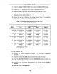
EQUIPMENT:
Interface
Box
Power Meter
Power Sensor
Power
Splitter
BNC(m)-BNC(m)
Adapter
BNC(m)-N(f) Adapter
BNC(m)-BNC(m)
Cable, 30 cm
PROCEDURE:
HP
PN
04284-65007
HP
436A
HP
8482A
HP
PN
04192-61001
HP
PN
1250-0216
HP
PN
1250-1477
HP
PN
8120-1838
1.
Calibrate the Power Meter for the Power Sensor.
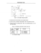
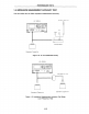
2. Set up the equipment
as
shown in Figure 1-4.
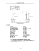
NOTE
If the Interface Box is not available, use the following cables and adapters
as
a substitute. Figure 1-5 shows the test setup without the interface box.
BNC(m)-BNC(m) Cable, 30 cm
Tee, BNC(m)(f)(f) Adapter
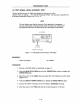
3. Set the Power Meter to
WATT.
HP
PN
8120-18382
ea.
HP
PN
1250-0781
4. Perform a
SYSTEM
RESET
as
described on page 1-4.
5.
Move the cursor to the
FREQ
field and set the test frequency to 3 MHz.
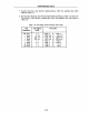
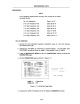
6.
Set the Power Meter CAL
FACTOR
% dial setting to the Power Sensor's CAL
FACTOR.
7. Record the Power Meter reading into Calculation Sheet column [a].
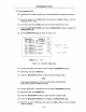
8.
Calculate the test signal voltage according to the Calculation Sheet, and record it
into column [b]. Figure 1-6 explains the voltage calculation theory.
1-9