
Specifications

PERFORMANCE TESTS
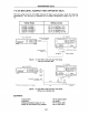
52. Connect the 0 n Termination (04191-85030) to the Terminal Adapter's OUTPUT
terminal.
53. Move the cursor
to
the
SHORT
field.
54. Press the 'MEAS SHORT' softkey to store the short correction data.
55. Press the
'DISPLAY FORMAT MENU' key to display the MEAS DISPLAY page.
56. Connect the
20 cm Air Line to the Terminal Adapter's
OUTPUT
terminal.
57. Connect the
0 S Termination
to
the 20 cm Air Line.
58. Move the cursor to
LEVEL field, and set the test signal level
to
1
V.
59. Move the cursor to
FREQ
field, and set the test frequency to
1.1
MHz.
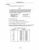
60. Press the TRIGGER key, and confirm that the
HP
4285A's reading
is
within the
specified test
limits listed in Table 1-8.
61. Perform the test for
all settings listed in Table 1-8, by repeating steps 58 to step
60 for each listed setting.
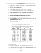
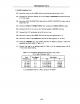
Table 1-8. Impedance Measurement Accuracy Test Limits
(0
m High Frequency Test)
Test Test
Signal
Test Limits
Frequency
Level
Cp
D
1.1
MHz 1
V
C.V.±0.032
pF
±0.0023
1.1
MHz
2 V
C.V.±0.028
pF
±0.0020
2 MHz 1 V C.V.±0.030
pF
±0.0022
2 MHz 2 V C.V.±0.044
pF
±0.0032
5 MHz
1 V
C.V.±0.051
pF
±0.0037
5 MHz
2 V
C.V.±0.047
pF
±0.0034
10
MHz
20 mV C.V.±0.221
pF
±0.0158
10
MHz 100 mV C.V.±0.114
pF
±0.0082
10
MHz
1 V
C.V.±0.114
pF
±0.0082
10
MHz 2 V
C.V.±0.100
pF
±0.0072
20
MHz 1 V
C.V.±0.246
pF
±0.0176
20
MHz 2 V C.V.±0.281 pF ±0.0201
30
MHz 1 V C.V.±0.536
pF
±0.0383
30
MHz 2 V C.V.±0.509
pF
±0.0364
C.V.:Calibrated Value
at 1 MHz, using
an
HP
4284A
1 m Low Frequency Test
62. Move the cursor to the LEVEL
field, and set the test signal level
to
0.5
V.
63. Press the CATALOG SYSTEM MENU key and 'CABLE CORREC' softkey to dis-
play the CABLE CORRECTION page.
1·19