
User`s guide

1 Introduction
10 Agilent N1913/1914A EPM Series Power Meters User’s Guide
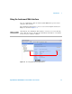
The Display Layout
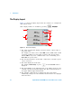
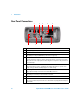
Figure 1- 1 shows the display layout when two windows are configured in
dual numeric mode.
Other display formats are available by pressing ,
.
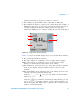
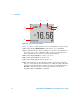
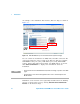
Figure 1-1 Dual numeric display
1 The status reporting line displays messages and the control status of
the power meter.
For example, the status can be either RMT (remote, GPIB, USB or LAN
operation) or LCL (local, front panel operation). The message fields
indicate ERR for any error conditions that occur or informing you to
Please Zero the power sensor.
2 The measured channel is shown with a 8480 Series or E- Series power
sensor connected.
3 This field displays the menu title.
For example, Channel Setup or press and the Zero/Cal menu is
displayed.
4 The blue highlight on the right hand side of the window shows it is the
currently selected measurement display line. This measurement line is
the Upper Window/Upper Measurement.
5 The available softkey labels are displayed in these three fields.
Additionally, settings associated with the labeled function are displayed
under the label.
Disp Type
1
2
3
4
5
7
6