
User`s guide


General Power Meter Functions 2
N1913/1914A EPM Series Power Meters User’s Guide 41
Setting Frequency Dependent Offsets
Frequency dependent offset tables provide a quick and convenient method
of compensating for frequency related changes in the response of your test
system. Note that when selected, frequency dependent offset corrections
are applied IN ADDITION to any correction for sensor frequency response.
The power meter is capable of storing 10 frequency dependent offset
tables with a maximum of 80 frequency points each.
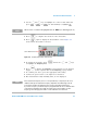
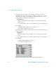
To use frequency dependent offset tables:
1 Select the table to be applied to a channel. Refer to “Setting Frequency
Dependent Offsets” on page 41 for further information. If you require to
edit the table refer to “Editing Frequency Dependent Offset Tables” on
page 44 for further information.
2 If an 8480 Series, N8480 Series, an E- Series, or an U2000 Series sensor
is used, zero and calibrate the power sensor. The reference calibration
factor used during the calibration is automatically set by the power
meter from the sensor calibration table (if selected).
3 Specify the frequency of the signal you want to measure. The
calibration factor/offset is automatically set by the power meter from
the sensor calibration table (if selected) and the frequency dependent
offset table. Refer to “Procedure” on page 42 for further information.
4 Make the measurement.
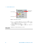
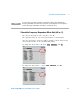
Selecting a Frequency Dependent Offset Table
You can select a frequency dependent offset table from the key
menu followed by , , and for Channel A or
Channel B.
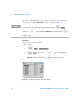
For Channel C, you can select the frequency dependent offset table from
the key menu followed by , , and .
For Channel D, you can select the frequency dependent offset table from
the key menu followed by , , and .
Tab les
Meter
Freq. Dep. Offset
Tab les
Sensor ChC
Freq. Dep. Offset
Tab les
Sensor ChD
Freq. Dep. Offset